


Chapter 4 Explanation of Functions
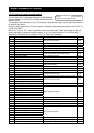
Item Function code Data or range of data Description
33
LOG1: Logical operation result 1
(C142, C143, and C144)
34
LOG2: Logical operation result 2
(C145, C146, and C147)
Terminal function
35
LOG3: Logical operation result 3
(C148, C149, and C150)
36
LOG4: Logical operation result 4
(C151, C152, and C153)
37
LOG5: Logical operation result 5
(C154, C155, and C156)
Alarm relay
terminal function
C021 to C025
C026
38
LOG6: Logical operation result 6
(C157, C158, and C159)
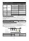
Logical output
signal selection 1
C142/C145/C148/
C151/C154/C157
Selection of "00" to "56" from the
data (except LOG1 to LOG6) output
to intelligent output terminals
Selection of operation-target 1
Logical output
signal selection 2
C143/C146/C149/
C152/C155/C158
Selection of "00" to "56" from the
data (except LOG1 to LOG6) output
to intelligent output terminals
Selection of operation-target 2
00 AND
01 OR
Logical output
signal operator
selection
C144/C147/C150/
C153/C156/C159
02 XOR
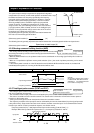
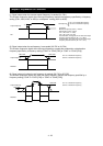
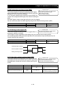
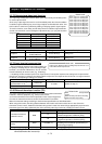
4.2.67 Capacitor life warning signal (WAC)
C021 to C025: Terminal [11] to [15] functions
C026: Alarm relay terminal function
Related code
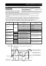
The inverter checks the operating life of the capacitors on the
internal circuit boards on the basis of the internal temperature
and cumulative power-on time.
You can monitor the state of the capacitor life warning (WAC) signal by using the life-check monitoring
function (d022).
If the WAC signal is output, you are recommended to replace the main circuit and logic circuit boards.
Item Function code Data or range of data Description
Terminal function C021 to C025
Alarm relay terminal function C026
39
WAC: Capacitor life warning signal
(for on-board capacitors)
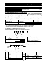
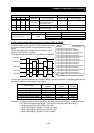
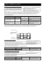
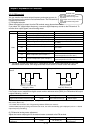
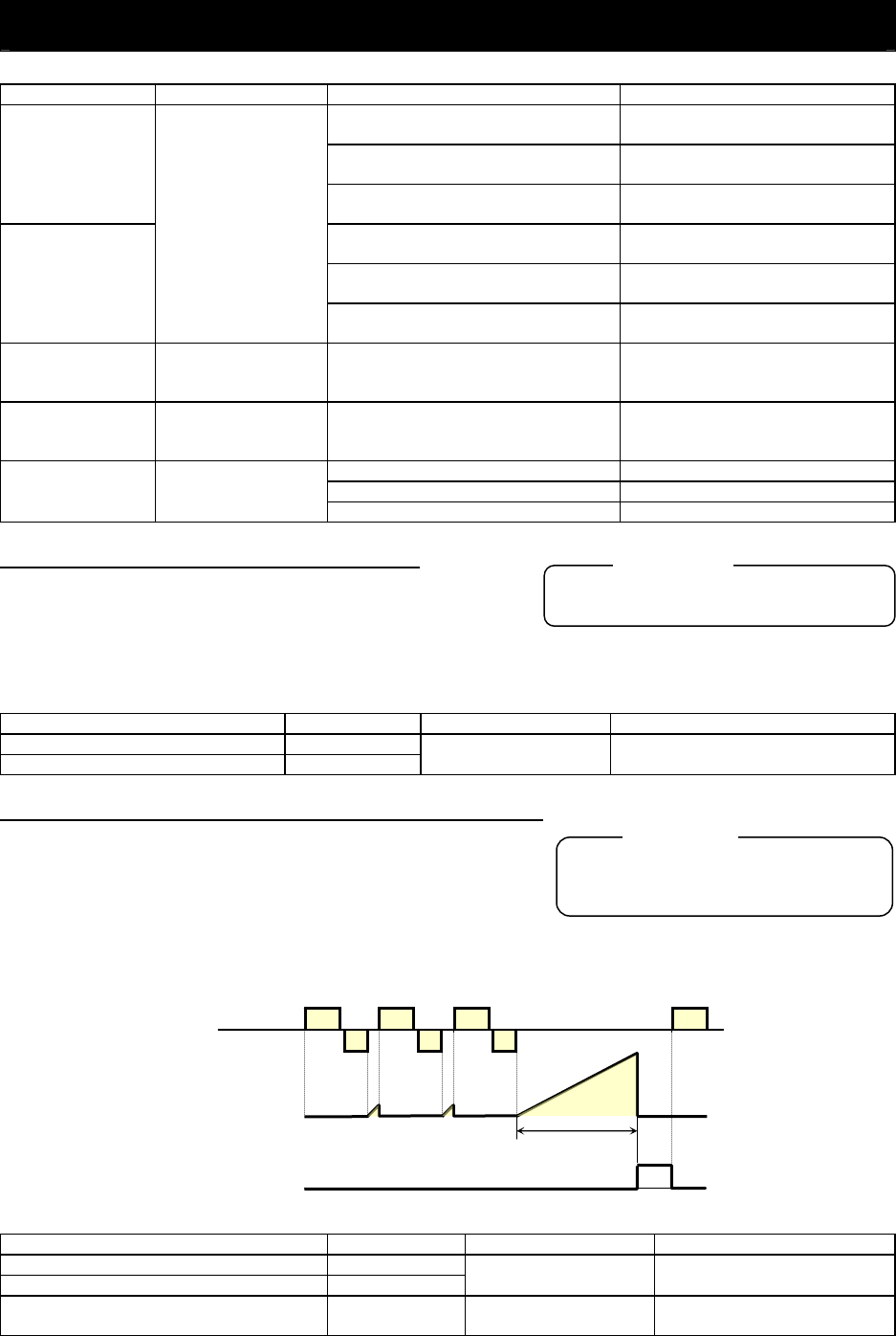
4.2.68 Communication line disconnection signal (NDc)
This signal function is enabled only when ModBus-RTU has been
selected for the RS485 communication.
C021 to C025: Terminal [11] to [15] functions
C026: Alarm relay terminal function
C077: Communication trip time
Related code
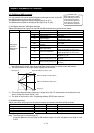
If a reception timeout occurs, the inverter continues to output the
communication line disconnection signal until it receives the next
data.
Specify the limit time for reception timeout by setting the communication trip time (C077).
For details, see Section 4.4, "Communication Functions."
(C077)
External control equipment
Inverter
Monitoring timer
Communication line
disconnection signal (NDc)
Communication trip time
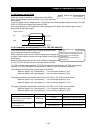
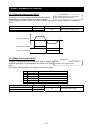
Item Function code Data or range of data Description
Terminal function C021 to C025
Alarm relay terminal function C026
32
NDc: Communication line
disconnection signal
Communication trip time C077 0.00 to 99.99 (s)
Setting of the limit time for
reception timeout
4 - 67