


Chapter 3 Operation
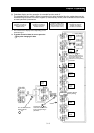
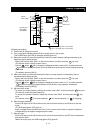
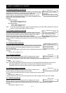
Braking unit
Moto
r
DC reactor
H
L
O
H
R
S
T
T
R
S
P24
PLC
CM1
TH
FM
1
8
(RV)
FW
A
MI
L
A
M
O2
OI
O
ELB
U
V
W
PD
P
RB
N
A
L0
A
L1
A
L2
11
15
CM2
SP
SN
RP
SN
G
Default: for sinking type
Digital operator
Type-D grounding (200 V class model)
Type-C grounding (400 V class model)
3-phase
power supply
Operating box
(OPE-4MJ2)
(OPE-8MJ2)
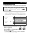
(Operating procedure)
1) Confirm that all wirings are correct.
2) Turn on the earth-leakage breaker (ELB) to supply power to the inverter.
(The POWER lamp [red LED] of the digital operator goes on.)
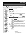
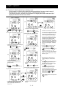
3) Select the control circuit terminal block as the device to input frequency-setting commands by the
frequency source setting function.
- Display the function code "A001" on the monitor screen, and then press the key once.
FUNC
(The monitor shows a 2-digit numeric value.)
- Use the and/or key to change the displayed numeric value to [01], and then press the
key once to specify the control circuit terminal block as the device to input frequency-setting
commands.
2
1
STR
(The display reverts to [A001].)
4) Select the control circuit terminal block as the device to input operation commands by the run
command source setting function.
- Display the function code "A002" on the monitor screen, and then press the key once.
FUNC
(The monitor shows a 2-digit numeric value.)
- Use the and/or key to change the displayed numeric value to "01", and then press the
key once to specify the digital operator as the device to input operation commands.
2
1
(The display reverts to [A002].)
STR
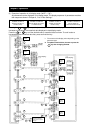
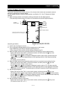
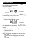
5) Set the monitor mode.
- To monitor the output frequency, display the function code "d001", and then press the key once.
FUNC
(The monitor shows the output frequency.)
To monitor the operation direction, display the function code "d003", and then press the key
once.
FUNC
(The monitor shows for forward operation, for reverse operation, or for stopping.)
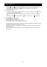
6) Start the motor operation.
- Set the FW signal (at the FW terminal on the control terminal block) to the ON level to start the
motor.
(The RUN lamp [green LED] goes on.)
- Apply a voltage across the terminals O and L on the control circuit block to output the frequency
corresponding to the applied voltage from the inverter.
7) Stop the motor.
- Set the FW signal (at the FW terminal on the control terminal block) to the OFF level to decelerate
and stop the motor.
(When the motor stops, the RUN lamp [green LED] goes off.)
3 - 13