


Chapter 4 Explanation of Functions
03
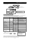
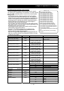
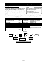
Multistage position setting 0
(P060)
04
Multistage position setting 0
(P060)
05
Multistage position setting 0
(P060)
06
Multistage position setting 0
(P060)
07
Multistage position setting 0
(P060)
Multistage speed/position
determination time
C169
0. to 200. X10ms
Position setting monitor d029
-1073741823 to + 1073741823
Position feedback monitor d030
-1073741823 to + 1073741823
54 SON: Servo-on
66 CP1: Position setting selection 1
67 CP2: Position setting selection 1
68 CP3: Position setting selection 1
69 ORL: Zero-return limit signal
70 ORG: Zero-return start signal
71 FOT: Forward drive stop
72 ROT: Reverse drive stop
73
SPD: Switching between speed
and position controls
C001-C008
45 ORT: Teaching
Reset mode selection C102
03
Internal data is not initialized by a
reset.
4.3.13 Operation in absolute position control mode
4 - 109
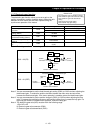
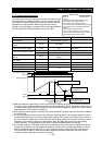
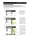
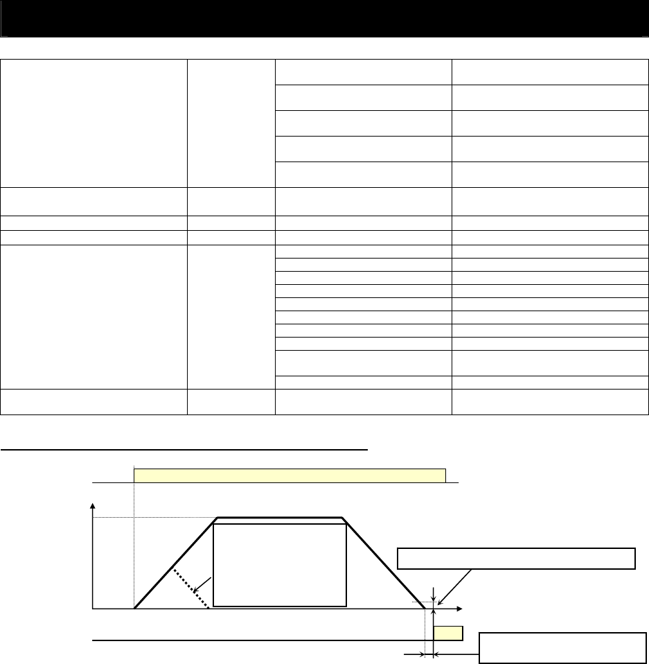
ON
Output frequency
Position
Speed setting
Operation
Home search completion range setting (P017)
If the position value
specified by the position
setting is small, the
inverter decelerates the
motor for positioning
before its speed reaches
Home search completion delay
time setting (P018)
ON
POK signal
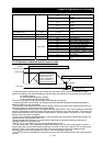
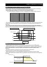
- In absolute position control mode, the inverter runs the motor until the machine reaches the target
position according to the following settings, and then sets the machine into the position servo-lock state:
<1> Position setting
<2> Speed setting (frequency setting)
<3> Acceleration and deceleration time
(The servo-lock state is held until the operation command is turned off.)
- In absolute position control mode, the frequency and acceleration/deceleration settings selected at
absolute position control are applied.
- If the position value specified by the position setting is small, the inverter may decelerate the motor for
positioning before its speed reaches the speed setting.
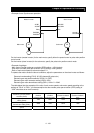
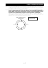
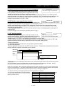
- In absolute position control mode, the rotating-direction setting (FW or RV) of the operation command is
ignored. The operation command simply functions as the signal to run or stop the motor. The motor runs
in the forward direction when the value of "target position - current position" is positive, or in the reverse
direction when the value is negative.
- If zero-return operation (described below) is not performed, the motor position detected at power-on is
assumed as the origin (position data = 0).
- When the operation command is turned on with 0 specified as the position setting, positioning is
completed without running the motor.
- Specify "03" (to only reset a trip) for reset mode selection (C102).
* If a value other than "03" is specified for reset mode selection (C102), the current position counter is
cleared when the inverter reset terminal (reset key) is turned on. Be sure to specify "03" for reset mode
selection (C102) if you intend to use the value of the current position counter for operation after
recovering the inverter from tripping by turning on the reset terminal (reset key).
- If the PCLR function is assigned to a terminal, turning on the PCLR terminal clears the current position
counter.