Chapter 4 Explanation of Functions
4.2.98 Torque monitoring function
A044/A244: V/F characteristic curve selection,
1st/2nd motors
C027: [FM] siginal selection
C028: [AM] siginal selection
C029: [AMI] siginal selection
H003/H203: Motor capacity, 1st/2nd motor
H004/H204: Motor poles setting, 1st/2nd motors
Related code
The torque monitoring function allows you to monitor the
estimated motor output torque when the V/F characteristic
curve selection is the sensorless vector control, 0Hz-range
sensorless vector control, or vector control with sensor.
To monitor the output torque on the digital operator, select
code "d012" on the digital operator.
To monitor the output torque as a signal output from the control circuit terminal block, see Section 4.2.77,
"FM terminal," or 4.2.78, "AM and AMI terminals."
If the constant torque characteristic (VC), reduced-torque characteristic (1.7th power of VP), or free V/f
characteristic is specified for the V/F characteristic curve selection (A044/A244), this function is disabled,
and the display on the digital operator and the signal output from the control circuit terminal block are
unpredictable.
The torque monitored by this function is displayed as a ratio to the torque the motor outputs when rotating
in synchronization with the frequency corresponding to the motor's rated output. (The latter torque is
100%.)
Since this function estimates the output torque from the motor current, the accuracy of monitoring is about
20% when the inverter drives a motor that has the same output ratings as the inverter.
Item Function code Data or range of data Description
03 Sensorless vector control
04 0Hz-range sensorless vector control
V/F characteristic curve
selection
A044/A244
05
Vector control with sensor (not available
for A244)
02 Output torque [FM] siginal selection
[AM] siginal selection
[AMI] siginal selection
C027
C028
C029
11 Output torque (signed) (only for C028)
Motor capacity selection H003/H203 0.20 to 75.0 (kW)
Motor pole selection H004/H204 2, 4, 6, 8, or 10 (poles)
4.2.99 Forcing function (FOC)
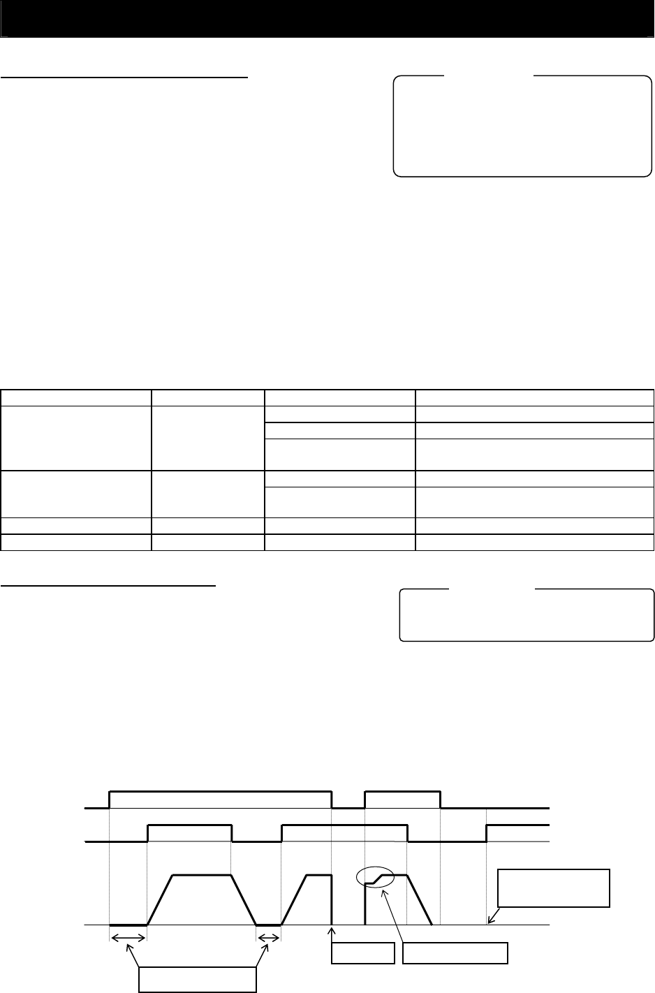
The forcing function allows you to apply an exciting
current via an input terminal to the inverter to pre-build magnetic
flux when "03" (sensorless vector control), "04" (0Hz-range
sensorless vector control), or "05" (vector control with sensor) is
specified for the V/F characteristic curve selection (A044/A244).
A044/A244: V/F characteristic curve selection,
1st/2nd motors
C001 to C008: Terminal [1] to [8] functions
Related code
To use this function, assign function "55" (FOC) to an intelligent input terminal.
After the FOC function is assigned, the inverter will accept operation commands only when the FOC
terminal is turned on.
If the FOC terminal is turned off while the inverter is operating the motor, the inverter sets the motor into
the free-running state. If the FOC terminal is turned on subsequently, the inverter restarts the motor
according to the setting of the restart mode after FRS (b088).
FOC
FW
(
RV
)
Restarting according to the
setting of "b088
"
Free running
The inverter does not operate
the motor because the FOC
terminal is off.
Exciting current flows.
Output frequency
4 - 92


