


Chapter 2 Installation and Wiring
(Examples of wiring)
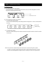
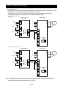
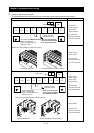
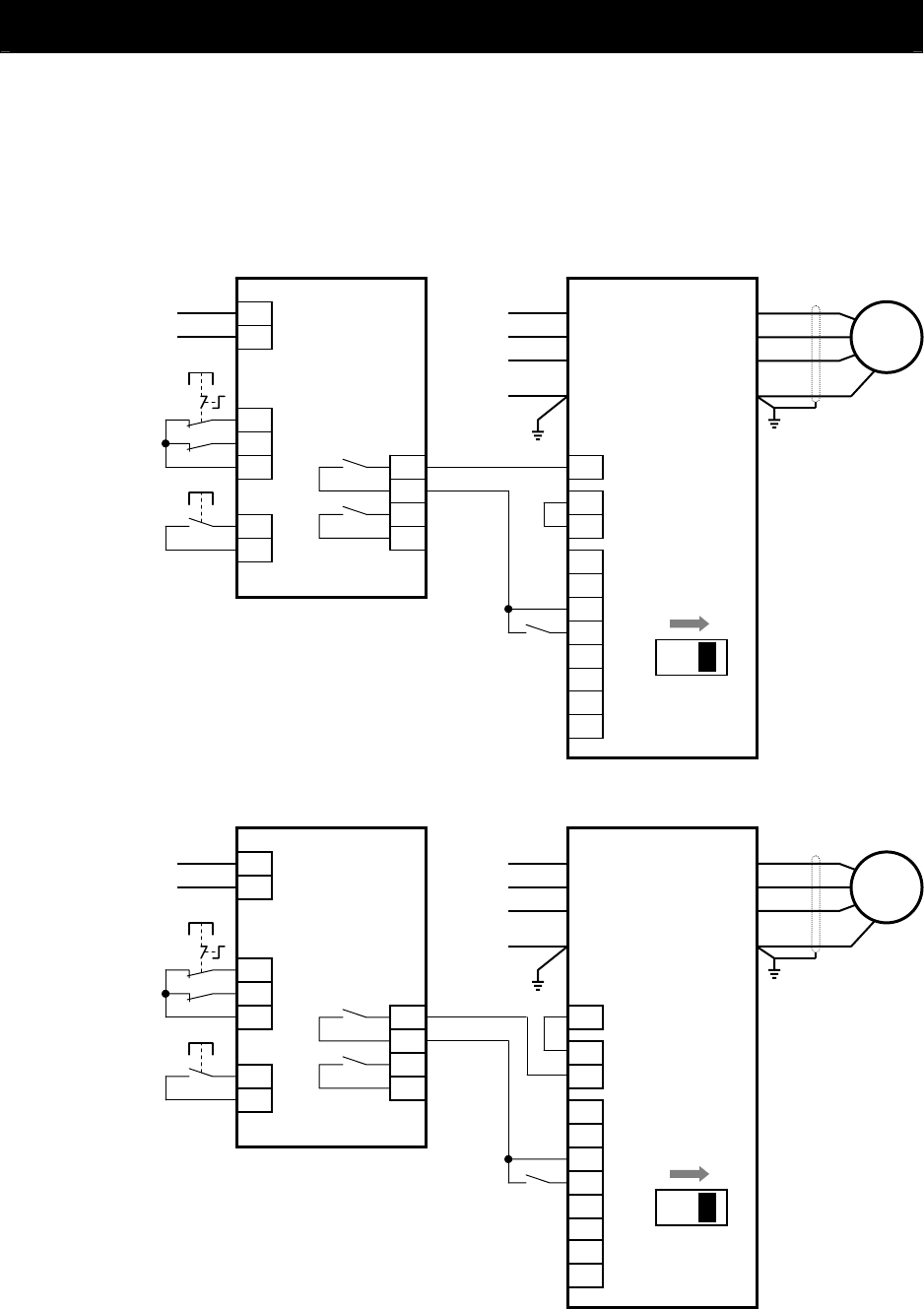
- The examples of wiring below are intended to implement the Safe Stop function through safety input of
the EMR signal by the method complying with EN954-1 Category 3.
- The emergency stop circuit is monitored via an external safety relay (safety switching device).
- One safety relay (safety switching device) can be used for multiple inverters.
6
7
8
R
R
S
S
T
T
G
G
PLC
PLC
CM1
1
2
3
4
5
EMR
RS
SW1 = ON
SJ700 inverter
U
V
W
G
A1
A2
S22
S12
S11
S13
Emergency
stop
S22
S12
S14
Start/stop
13
14
23
24
(PN0Z X5)
R (+)
M
Safety switching device
(Example of connection based on
source logic)
T (-)
6
7
8
R
R
S
S
T
T
G
G
P24
PLC
CM1
1
2
3
4
5
EMR
RS
SW1 = ON
SJ700 inverter
U
V
W
G
A1
A2
S22
S12
S11
S13
Emergency
S22
S12
S14
Start/stop
R (+)
T (-)
13
14
23
24
(PN0Z X5)
Safety switching device
(Example of connection based on
M
Note: The safety relay (safety switching device) used in these examples is the PNOZ X5 made by Pilz.
Use a safety switching device equivalent to the PNOZ X5.
2 - 12