


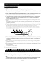
Chapter 2 Installation and Wiring
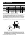
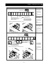
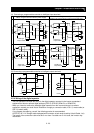
Terminal layout Inverter model
SJ700-300LFF
R0 and T0: M4
Ground terminal:
M6
Other terminals:
M8
SJ700-300HFF
R0 and T0: M4
Ground terminal:
M6
Other terminals:
M6
R
(L1)
S
(L2)
T
(L3)
PD
(+1)
P
(+)
N
(-)
U
(T1)
V
(T2)
W
(T3)
R0
T0
G
G
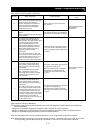
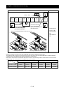
SJ700-370LFF
SJ700-370HFF
R0 and T0: M4
Ground terminal:
M8
Other terminals:
M8
R
(L1)
S
(L2)
T
(L3)
PD
(+1)
P
(+)
N
(-)
U
(T1)
V
(T2)
W
(T3)
R0
T0
charge lump
G
G
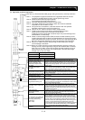
SJ700-450LFF2
SJ700-450HFF2
SJ700-550HFF2
R0 and T0: M4
Ground terminal:
M8
Other terminals: M8
2 - 17
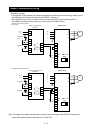
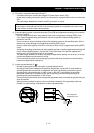
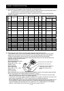
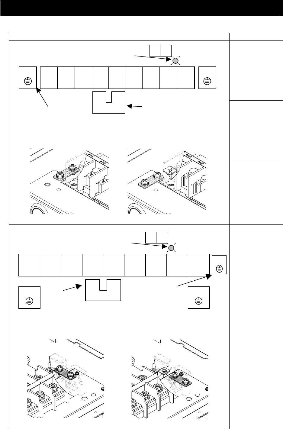
[Method of enabling/disabling the EMC filter function]
Jumper connecting
Terminals PD and P
Enabling the EMC filter
Disabling the EMC filter (factory setting)
Charge lamp
When not using the DCL,
do not remove the jumper
from terminals PD and P.
Ground terminal with
jumper (shaded in the
figure) to enable/disable the
EMC filter function
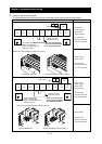
Jumper connecting
terminals PD and P
Enabling the EMC filter
Ground terminal with
jumper (shaded in the
figure) to enable/disable the
EMC filter function
G
When not using the DCL,
do not remove the jumper
from terminals PD and P.
Disabling the EMC filter (factory setting)
[Method of enabling/disabling the EMC filter function]