


Chapter 4 Explanation of Functions
4.2.97 Sensorless vector, 0 Hz domain control
A001: Frequency source setting
A044/A244: V/F characteristic curve selection,
1st/2nd motors
F001: Output frequency setting
b040: Torque limit selection
b041 to b044: Torque limit (1) to (4)
H002/H202: Motor data selection, 1st/2nd motors
H003/H203: Motor capacity, 1st/2nd motors
H004/H204: Motor poles setting, 1st/2nd motors
otoH005/H205: Motor speed constant, 1st/2nd m
H020/H2
rs
20: Motor constant R1, 1st/2nd motors
s
,
H021/H221: Motor constant R2, 1st/2nd motors
H022/H222: Motor constant L, 1st/2nd motors
H023/H223: Motor constant Io, 1st/2nd motors
H024/H224: Motor constant J, 1st/2nd motors
H050/H250: PI proportional gain, 1st/2nd motor
H051/H251: PI integral gain, 1st/2nd motors
nd H052/H252: P proportional gain setting, 1st/2
motors
H060/H260: Zero LV lmit, 1st/2nd motors
H061/H261: Zero LV starting boost current
1st/2nd motors
Related code
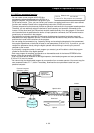
The 0Hz domain sensorless vector (SLV) control function
incorporates Hitachi’s own torque control system and
enables high-torque operation in the 0Hz range (0 to 3 Hz).
This control function is best suited for driving a lifting
machine, e.g., crane or hoist, that requires sufficient torque
when starting at a low frequency.
To use this function, specify "04" for the V/F characteristic
curve selection (A044/A244).
Before using this function, be sure to optimize constant
settings for the motor with reference to Section 4.2.91,
"Motor constant selection."
The parameters related to the 0Hz-range sensorless vector
control are as follows:
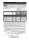
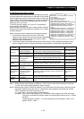
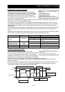
1) The Zero LV lmit for 1st/2nd motors (H060/H260) is the
parameter that specifies the output current for the constant-
current control in the 0 Hz range (about 3.0 Hz or less). The
parameter value is expressed as a ratio of the output current
to the inverter's rated current.
2) The Zero LV starting boost current (H061/H261) is the parameter to specify the current for boosting at
motor start-up with a frequency in the 0 Hz range. The parameter value is expressed as a ratio of the
boost current to the inverter's rated current. The value of the boost current is added to the current value
specified by "H060/H260" only at starting.
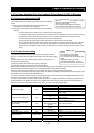
Item Function code Range of data Description
Zero LV lmit H060/H260 0.0 to 100.0 (%) Current limiter for the low-speed range
Zero LV starting boost current H061/H261 0. to 50. (%) Quantity of boost current at starting
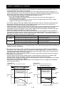
When using this function, observe the following precautions:
1) Be sure to use an inverter of which the capacity is one class higher than the motor to be driven.
2) If you use the inverter to drive a motor of which the capacity is two classes lower than the maximum
applicable capacity of the inverter, you may not be able to obtain adequate motor characteristics.
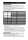
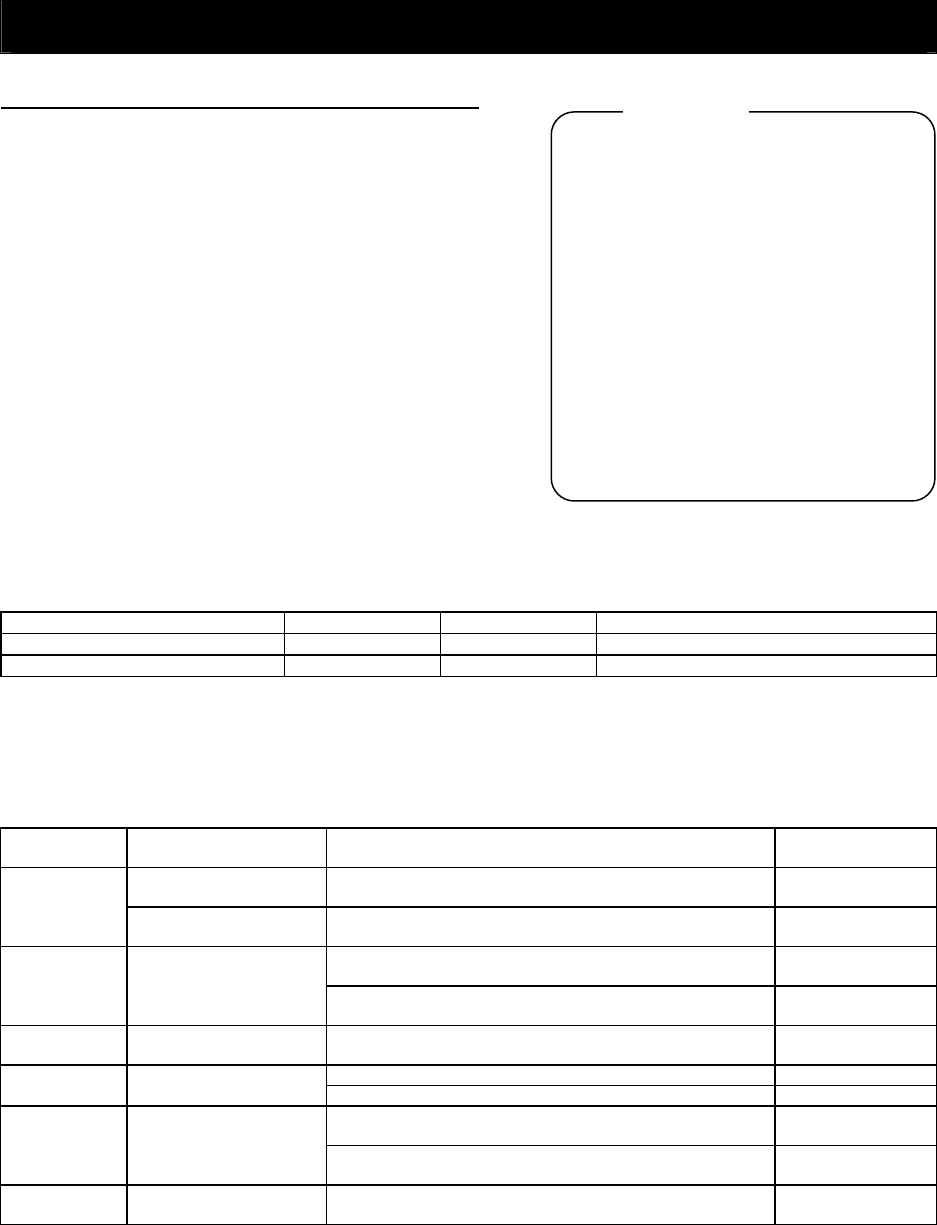
3) If you cannot obtain desired characteristics from the motor driven under the 0Hz-range sensorless
vector control, readjust the motor constants according to the symptom as described in the table below.
Operation
status
Symptom Adjustment method Adjustment item
Momentary speed
variation is negative.
Increase the motor constant R2 step by step from the
set value up to 1.2 times as high as the set value.
H021/H221/H031
Powering
Momentary speed
variation is positive.
Reduce the motor constant R2 step by step from the
set value down to 0.8 times as high as the set value.
H021/H221/H031
Increase the motor constant R1 step by step from the
set value up to 1.2 times as high as the set value.
H020/H220/H030
Regenerating
Torque is insufficient at
low frequencies
(several Hz)
Increase the motor constant I0 step by step from the
set value up to 1.2 times as high as the set value.
H023/H223/H033
Starting
The motor generates an
impact when it starts.
Reduce the motor constant J from the set value. H024/H224/H034
Reduce the speed response setting. H005/H205
Decelerating
The motor runs
unsteadily.
Reduce the motor constant J from the set value. H024/H224/H034
Reduce the motor constant I0 step by step from the set
value down to 0.8 times as high as the set value.
H023/H223/H033
Immediately
after
deceleration
Overcurrent or
overvoltage protection
function operates.
Specify "00" (always on) or "01" (always off) for the
AVR function select (A081).
A081
Low-frequency
operation
Motor rotation is
inconsistent.
Increase the motor constant J from the set value. H024/H224/H034
Note 1: Always set the carrier frequency (b083) to 2.1 kHz or more. If the carrier frequency is less than
2.1 kHz, the inverter cannot operate the motor normally.
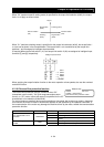
Note 2: Adjust the torque limit (b041 to b044) so that the value "α" calculated by the expression below
does not exceed 200%. Otherwise, the motor may be burnt out.
α = "torque limit" x (inverter capacity)/(motor capacity)
(Example) When the inverter capacity is 0.75 kW and the motor capacity is 0.4 kW, the torque
limit value is calculated as follows on the assumption that the value "α" should be
200%:
Torque limit (b041 to b044) = α x (motor capacity)/(inverter capacity) = 200% x (0.4
kW)/(0.75 kW) = 106%
4 - 91