


Chapter 2 Installation and Wiring
2 - 18
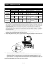
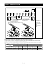
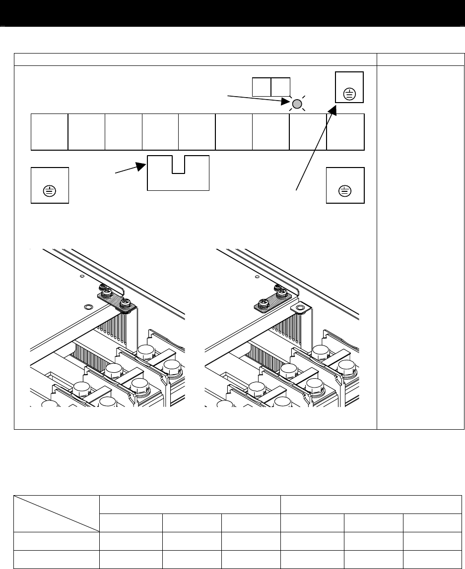
Terminal layout Inverter model
R
(L1)
S
(L2)
T
(L3)
PD
(+1)
P
(+)
N
(-)
U
(T1)
V
(T2)
W
(T3)
R0
T0
charge lump
G
G
SJ700-550LFF2
R0 and T0: M4
Ground terminal:
M8
Other terminals:
M10
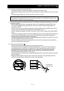
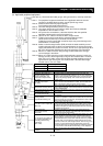
When not using the DCL,
do not remove the jumper
from terminals PD and P.
Ground terminal with
jumper (shaded in the
figure) to enable/disable the
EMC filter function
Jumper connecting
Terminals PD and P
G
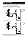
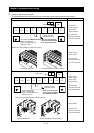
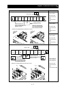
[Method of enabling/disabling the EMC filter function]
Disabling the EMC filter (factory setting)
Enabling the EMC filter
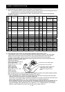
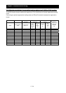
Reference: Leakage current by inverter with model EMC filter enabled or disabled (reference data)
The table below lists the reference currents that may leak from the inverter when the internal EMC filter is enabled or disabled.
(Leakage current is in proportion to the voltage and frequency of input power.)
Note that the values listed in the table below indicate the reference currents leaking from the inverter alone. The values exclude
current leakage from external devices and equipment (e.g., power cables).
200 V class model (input power: 200 VAC, 50 Hz) 400 V class model (input power: 400 VAC, 50 Hz)
5.5kW~11kW 15kW~37kW 45kW~55kW 5.5kW~11kW 15kW~37kW 45kW~55kW
Internal EMC filter enabled
Ca 48mA Ca 23mA Ca 23mA Ca.95mA Ca.56mA Ca.56mA
Internal EMC filter disabled
Ca.0.1mA Ca.0.1mA Ca.0.1mA Ca.0.2mA Ca.0.2mA Ca.0.2mA