Chapter 4 Explanation of Functions
Note 1: Since the inverter positions the motor shaft within two turns while decelerating the motor, do not
specify a high frequency as the home search speed. Otherwise, the inverter may trip during home
search because of the overvoltage protection function.
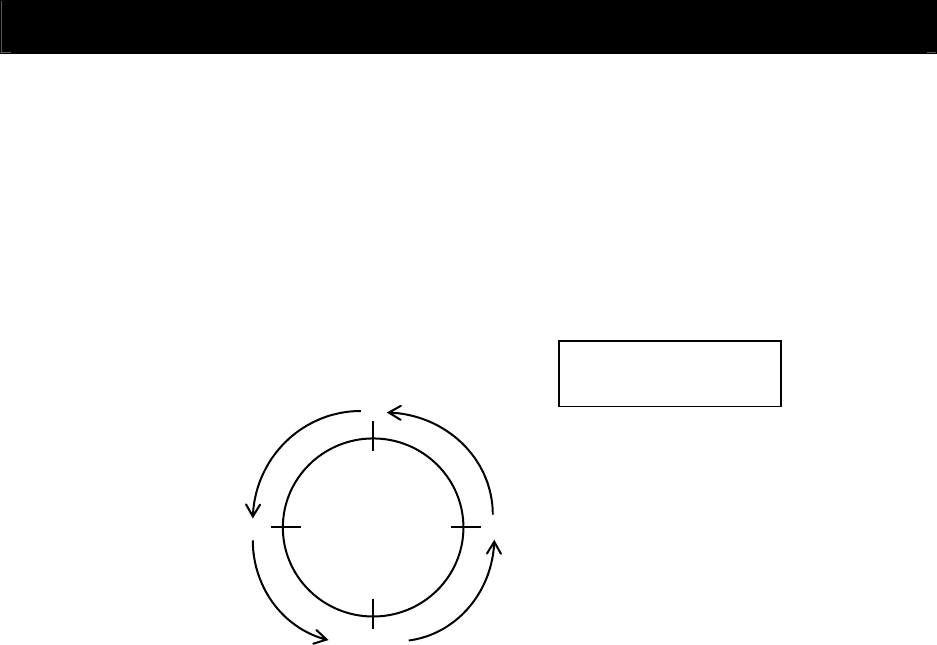
Note 2: For setting the home search stop position, the periphery of the motor shaft is divided into 4,096
sections to determine points No. 0 to No. 4095, beginning at the reference point in the direction of
forward rotation. (The division into 4,095 sections is irrelevant to the encoder pulse-per-revolution
(PPR) setting.) The reference point is specified as the point at which the Z pulse inserted
between the EZP pulse and EZN pulse signals is detected. Figure 7-2 shows the layout of the
reference point and target stop positions on the periphery of the motor shaft viewed from the load
side of the motor shaft (in case of positive-phase connection).
4 - 107
1024
3072
2048
0
Motor shaft viewed from
the motor load side
Position indicated by Z pulse
Reference point


