


Chapter 2 Installation and Wiring
2 - 13
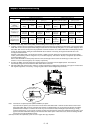
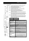
(Outline of operation)
- S13: Emergency stop button to switch the inverter into safe stop mode and the motor into free-running
status
- S14: Start/stop button
- Switches the inverter into safe stop mode by EMR signal input to a digital input terminal and sets the
motor into free-running status.
(This operation corresponds to EN60204-1 Stop Category 0.)
- Safe stop mode continues as long as the EMR signal is input or until the RS signal is input even after the
EMR signal is canceled.
- To use the inverter for an application in which a mechanical brake (such as for a crane) must be
controlled, the safety output from an external safety relay must be serially connected to the brake
control circuit.
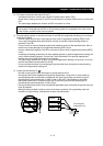
Note: The cables used for safety relay wiring, the EMR signal, and RS signal must be shielded coaxial
cables, such as type RG174/U complying with MIL-C17 (made by LAPP) or KX3B complying with NF
C 93-550. Each cable must be 2.8 mm in outer diameter and 2 m or less in length. The cable shielding
must be grounded.
Note: Every inductor-related device, such as a relay or contactor, must have an overvoltage protection
circuit.