


Chapter 2 Installation and Wiring
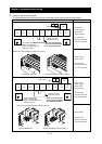
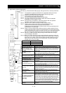
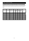
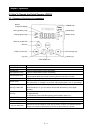
(4) Connecting a programmable controller to intelligent input terminals
When using the internal interface power supply
When using an external power supply
(Remove the jumper from the control circuit terminal block.)
Sink logic
Source logic
Inverter
PLC
8
COM
YTR48 type
output module
S
DC24V
FW
CM1
DC24V
P24
Inverter
YTR48 type
output module
Jumper
S
COM
P24
PLC
CM1
FW
8
DC24V
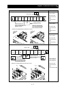
Inverter
YTS48 type
output module
DC24V
DC24V
COM
S
P24
PLC
CM1
8
FW
DC24V
Inverter
YTS48 type
output module
S
COM
P24
PLC
CM1
FW
8
Jumper
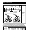
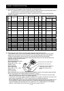
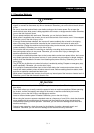
(5) Connecting a programmable controller to intelligent output terminals
Sink logic
Source logic
XDC24D2H
Inverter
11
12
CM2
COM
DC24V
DC24V
COM
CM2
12
XDC24D2H
11
Inverter
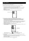
2.2.4 Wiring of the digital operator
- You can operate the inverter with not only the digital operator mounted in the inverter as standard
equipment but also an optional digital operator (OPE-S, OPE-SR, SRW-OJ, or SRW-OEX).
- When you intend to remove the standard digital operator from the inverter and use it as remote
equipment, request your local Hitachi Distributor to supply a connection cable, ICS-1 (1-meter cable) or
ICS-3 (3-meter cable).
If you prepare the cable by yourself, the following product is recommended:
HUTP5 PC 4P -X-X: Straight cable equipped with connector at both ends (made by Hitachi Cable, Ltd.)
- The length of the connection cable must be 3 m or less. If a cable over 3 m is used, the inverter may
malfunction.
2 - 23