


Chapter 4 Explanation of Functions
P028: Numerator of the motor gear ratio
P029: Denominator of the motor gear ratio
P011: Encoder pulse-per-revolution (PPR)
setting
Related code
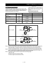
4.3.8 Motor gear ratio setting function
The motor gear ratio setting function allows you to make the
inverter effectively control a specific machine in which an encoder
is installed at the opposite end of the motor.
Specify the actual pulse count of the encoder as the encoder pulse-per-revolution (PPR) setting (P011).
Specify the ratio of the motor speed to the encoder speed as the motor gear ratio (numerator "P028" and
denominator "P029").
According to the above settings, the encoder pulse-per-revolution (PPR) setting data converted into motor
shaft data is set in the inverter.
The encoder pulse-per-revolution (PPR) setting data converted into motor shaft data is used to detect
speeds and positions. The data specified as the encoder pulse-per-revolution (PPR) setting (P011) is
used to calculate the home search stop position.
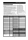
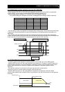
Item Function code Range of data Description
Numerator of the motor gear ratio P028 0. to 9999
Denominator of the motor gear ratio P029 0. to 9999
Setting of the ratio of motor
speed to encoder speed
Encoder pulse-per-revolution (PPR)
setting
P011
128. to 9999., 1000 to 6553
(10000 to 65530) (pulses)
Setting of the actual pulse
count of encoder
Note 1: The motor gear ratio (N/D) must be within the following range:
1/50 ≤ N/D ≤ 20
N: Numerator of the motor gear ratio
D: Denominator of the motor gear ratio
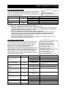
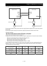
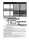
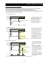
<Example of use>
Motor
Gear/load
(1:10)
Encoder
(1,024 pulses)
If the ratio of the motor speed to the encoder speed is 1:10, set the following data:
Encoder pulse-per-revolution (PPR) setting (P011): 1024
Numerator of the motor gear ratio (P028): 10
Denominator of the motor gear ratio (P029): 100
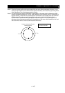
In this case, the periphery of the encoder shaft is divided into 4,096 sections to determine the points for
home search. Note that the conceptual layout of the home search stop position is inverted from that
shown in Figure 7-2.
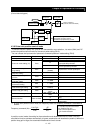
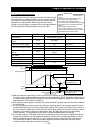
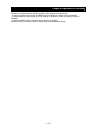
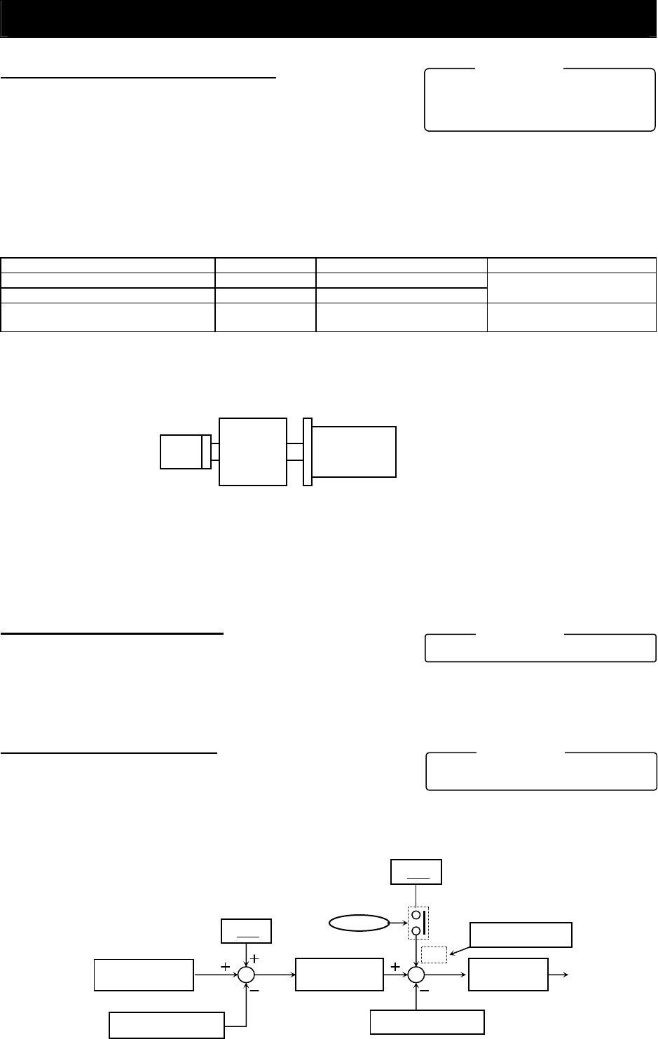
4.3.9 Position biasing function
- The position biasing function allows you to make the position
command bias during operation in pulse train position control
mode. This function adds the specified number of pulses to the variation of position data every 2 ms.
Use this function to adjust the phase of the synchronization point during synchronous operation.
P024: Position bias
q
uantit
y
Related code
- Specify the quantity to be added as the position bias quantity (P024).
4.3.10 Speed biasing function
A145: Additional-frequency setting
A146: Additional-frequenc
y
si
g
n selection
Related code
- This function allows you to make the speed command bias
during operation in pulse train position control mode.
- Specify the bias quantity for the additional-frequency setting (A145), and select a sign through
additional-frequency sign selection (A146).
- Assign function "50" (ADD) to an intelligent input terminal. The speed command is biased by the
specified quantity while the ADD terminal is on.
4 - 105
Variation of position
command
Variation of position
feedback
data
P024
Position biasing
Position control
Speed feedback data
Speed control
A145
Speed biasing
ADD
terminal
+/
-
Selected by A146