


Chapter 4 Explanation of Functions
C001-C008 intelligent input terminals
Related code
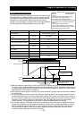
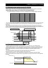
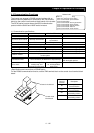
4.3.17 Forward/reverse drive stop function (FOT/ROT)
- The forward/reverse drive stop function allows you to prevent
motor operation from deviating from the specified control range
according to signals from the control range limit switches.
- When the FOT terminal is turned on, the torque for forward rotation is limited to 10%. When the ROT
terminal is turned on, the torque for reverse rotation is limited to 10%. This function can be used as a limit
switch function at the machine end. This function is activated by setting 71 (FOT) and 72 (ROT) on
intelligent input terminals 1-8 (C001- C008
4 - 113
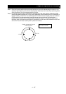
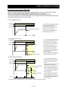
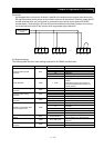
4.3.18 Position range specification function
- The position control ranges for forward and reverse rotations can
be specified by the position range specification (forward) (P072) and
position range specification (reverse) (P073), respectively. If the value of the current position counter
exceeds one of these ranges, a position control range error (E63.* or E73.*) causes the inverter to trip
and enter free-running status.
P072: Position range specification (forward)
P073: Position ran
g
e s
p
ecification
(
reverse
)
Related code
- The values specified by P072 and P073 limit the maximum values of multistage position settings 0 to 7
(P060 to P067).
(Position settings cannot exceed the specified position ranges.)
C001-C008 intelligent input terminals
P012: Control pulse setting
P
0
1
3
: H
o
m
e
sea
r
c
h
s
t
op
pos
iti
o
n
se
ttin
g
Related code
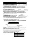
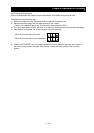
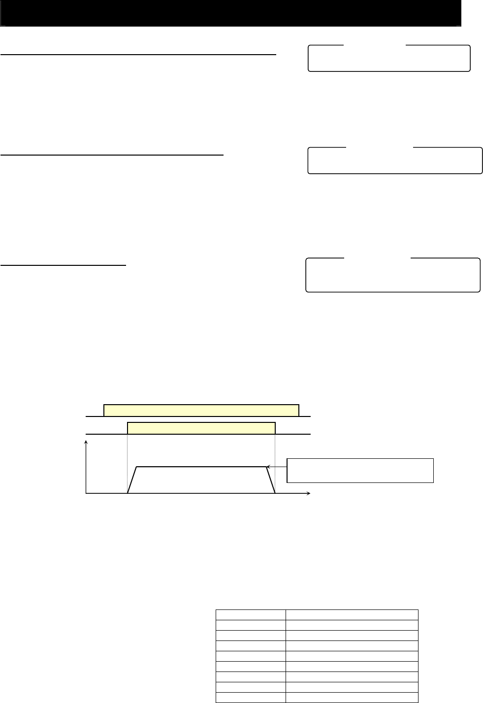
4.3.19 Teaching function
- The teaching function allows you to make the inverter run and
stop the motor arbitrarily, and then store position data as a position
command in an arbitrary position command area of memory.
- Assign function "45" (ORT) to an intelligent input terminal 1-8 (C001-C008).
The ORT terminal functions as the teaching terminal when "02" (absolute position control) or "03" (high-
resolution absolute position control) is specified for the control pulse setting (P012).
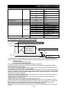
<Teaching procedure>
<1> Select the position command to be set by teaching selection (P074).
<2> Move the workpiece.
- Enter an operation command with the ORT terminal turned on. The speed and acceleration/deceleration
settings selected at operation command input are applied.
ON
Operation command
The speed setting selected at operation
command input is applied.
ON
Position
ORT terminal
Output
frequency
* Teaching operation can be performed when power is input to the power supply terminals (R0 and T0) of the inverter
control circuit.
The current position counter also operates when an external device moves the workpiece. Therefore, teaching
operation can also be performed when the inverter does not operate the machine.
Note: In the case above, make sure that the power supply to the power terminals (R, S, and T) of the inverter power
circuit or inverter output (U, V, and W) is disconnected from the motor. Performing teaching operation with the power
supply and inverter output connected may result in personal injury or damage to equipment.
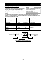
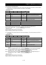
<3> Press the STR key on the digital operator when the target position is reached.
<4> The current position data is set in the memory area
corresponding to the position command specified by the
teaching selection (P074).
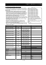
Setting of P074 Position command to be set
00 P060: Multistage position setting 0
01 P061: Multistage position setting 1
02 P062: Multistage position setting 2
03 P063: Multistage position setting 3
04 P064: Multistage position setting 4
05 P065: Multistage position setting 5
06 P066: Multistage position setting 6
07 P067: Multistage position setting 7