


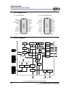

EM78P259N/260N
8-Bit Microprocessor with OTP ROM
10 •
Product Specification (V1.2) 05.18.2007
(This specification is subject to change without further notice)
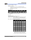
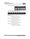
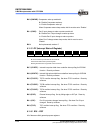
Bit 3 & Bit 2 (RCM1, RCM0): IRC mode selection bits
RCM 1 RCM 0 Frequency (MHz)
1 1 4 (default)
1 0 8
0 1 1
0 0 455kHz
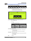
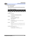
6.1.8 R8 (AISR: ADC Input Select Register)
The AISR register individually defines the pins of Port 5 as analog input or as digital I/O.
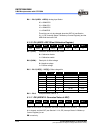
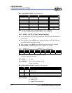
Bit 7 Bit 6 Bit 5 Bit 4 Bit 3 Bit 2 Bit 1 Bit 0
– – – – ADE3 ADE2 ADE1 ADE0
Bit 7 ~ Bit 4: Not used
Bit 3 (ADE3): AD converter enable bit of P53 pin
0 = Disable ADC3, P53 functions as I/O pin
1 = Enable ADC3 to function as analog input pin
Bit 2 (ADE2): AD converter enable bit of P52 pin
0 = Disable ADC2, P52 functions as I/O pin
1 = Enable ADC2 to function as analog input pin
Bit 1 (ADE1): AD converter enable bit of P51 pin
0 = Disable ADC1, P51 functions as I/O pin
1 = Enable ADC1 to function as analog input pin
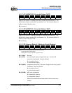
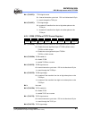
Bit 0 (ADE0): AD converter enable bit of P50 pin.
0 = Disable ADC0, P50 functions as I/O pin
1 = Enable ADC0 to function as analog input pin