


EM78P259N/260N
8-Bit Microprocessor with OTP ROM
52 •
Product Specification (V1.2) 05.18.2007
(This specification is subject to change without further notice)
When an interrupt is generated by the High time down counter underflow (if enabled),
the next instruction will be fetched from Address 018 and 01BH (High time and Low
time, respectively).
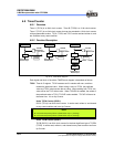
6.8.2 Function Description
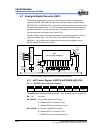
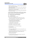
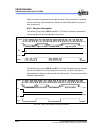
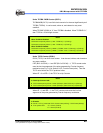
The following figure shows LGP=0 and HF=1. The IROUT waveform modulates the
Fcarrier waveform at low time segments of the pulse.
Fig. 6-12a LGP=0, HF=1, IROUT Pin Output Waveform
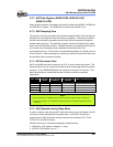
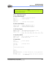
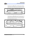
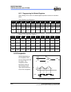
The following figure shows LGP=0 and HF=0. The IROUT waveform cannot modulate
the Fcarrier waveform at low time segments of the pulse. So IROUT waveform is
determined by the high time width and low time width instead. This mode can produce
standard PWM waveform
Fig. 6-12b LGP=0, HF=0, IROUT Pin Output Waveform
Fcarrier
IROUT
HF
IRE
high time widthlow time width high time width low time width
start
Fcarrier
IROUT
start
HF
IRE
high time widthlow time width high time width low time width