


EM78P259N/260N
8-Bit Microprocessor with OTP ROM
54 •
Product Specification (V1.2) 05.18.2007
(This specification is subject to change without further notice)
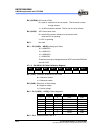
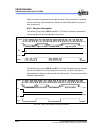
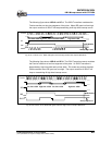
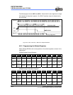
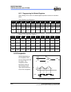
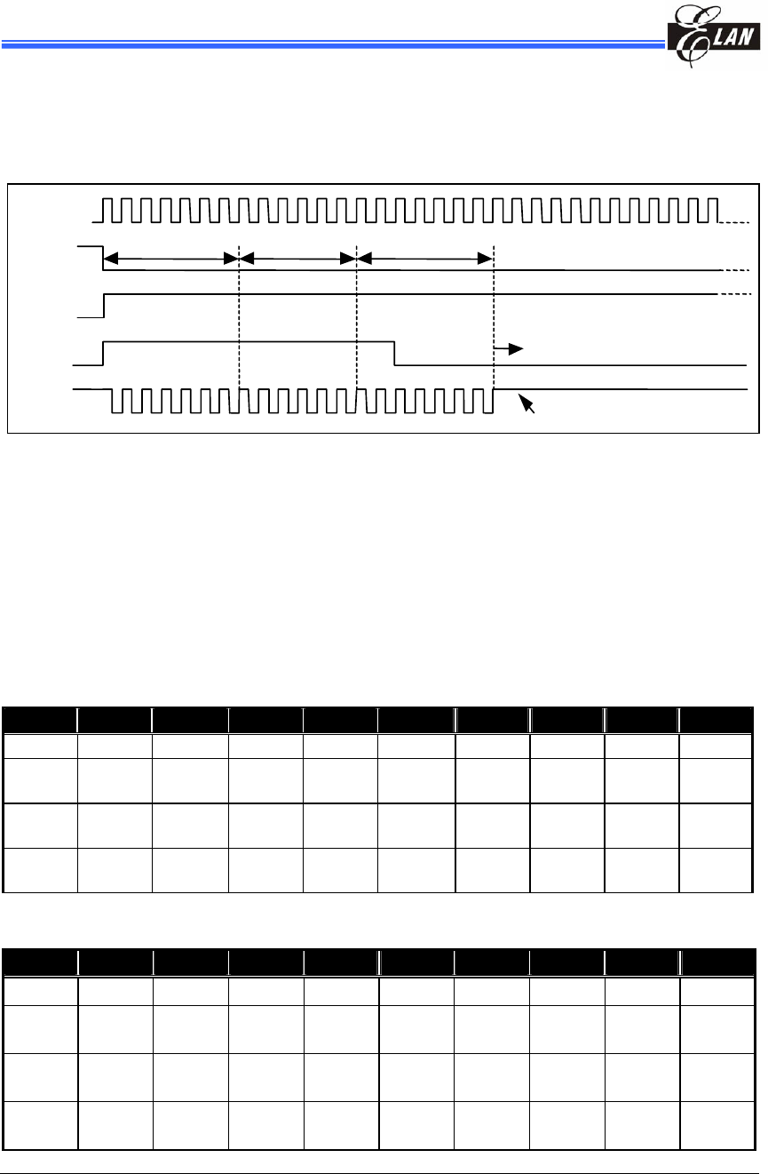
The following figure shows LGP=1 and HF=1. When this bit is set to high level, the high
time segment of the pulse is ignored. So, IROUT waveform output is determined by
low time width.
Fig. 6-12e LGP=1 and HF=1, IROUT Pin Output Waveform
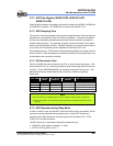
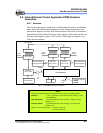
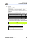
6.8.3 Programming the Related Registers
When defining IR/PWM, refer to the operation of the related registers as shown in the
tables below.
IR/PWM Related Control Registers
Address Name Bit 7 Bit 6 Bit 5 Bit 4 Bit 3 Bit 2 Bit 1 Bit 0
0x09 IOC90 TCCBHE/0 TCCBEN/0 TCCBTS/0 TCCBTE/0 0 TCCCEN/0 TCCCTS/0 TCCCTE/0
0X0A
IR CR
/IOCA0
TCCCSE/0 TCCCS2/0 TCCCS1/0 TCCCS0/0 IRE/0 HF/0 LGP/0 IROUTE/0
0x0F
IMR
/IOCF0
LPWTIE/0 HPWTIE/0 TCCCIE/0 TCCBIE/0 TCCAIE/0 EXIE/0 ICIE/0 TCIE/0
0X0B
HLTS
/IOCB1
HTSE/0 HTS2/0 HTS1/0 HTS0/0 LTSE/0 LTS2/0 LTS1/0 LTS0/0
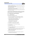
IR/PWM Related Status/Data Registers
Address Name Bit 7 Bit 6 Bit 5 Bit 4 Bit 3 Bit 2 Bit 1 Bit 0
0x0F ISR/RF LPWTIF/0 HPWTIF/0 TCCCIF/0 TCCBIF/0 TCCAIF/0 EXIF/0 ICIF/0 TCIF/0
0x06
TCCC
/IOC81
TCCC7/0 TCCC6/0 TCCC5/0 TCCC4/0 TCCC3/0 TCCC2/0 TCCC1/0 TCCC0/0
0X09
LTR
/IOC91
LTR7/0 LTR6/0 LTR5/0 LTR4/0 LTR3/0 LTR2/0 LTR1/0 LTR0/0
0X0A
HTR
/IOCA1
HTR7/0 HTR6/0 HTR5/0 HTR4/0 HTR3/0 HTR2/0 HTR1/0 HTR0/0
Fcarrier
IROUT
HF
IRE
IR disable
Always high-level
start
low time widthlow time width high time width low time width