


EM78P259N/260N
8-Bit Microprocessor with OTP ROM
Product Specification (V1.2) 05.18.2007
• 51
(This specification is subject to change without further notice)
6.8 Infrared Remote Control Application/PWM Waveform
Generation
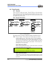
6.8.1 Overview
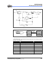
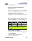
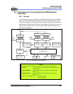
This LSI can easily output infrared carrier or PWM standard waveform. As illustrated
below, the IR and PWM waveform generation function include an 8-bit down count
timer/counter, high time, low time, and IR control register. The IROUT pin waveform is
determined by IOCA0 (IR and TCCC scale control register), IOCB1 (high time rate, low
time rate control register), IOC81 (TCCC counter), IOCA1 (high time register), and
IOC91 (low time register).
H/W Modulator
8
HF
IROUT
pin
IRE
Fcarrier
FT:CLK(Fosc)
LGP
8 Bit counter
8-to-1 MUX
8bit binary
down counter
Auto-reload buffer
(TCCC)(IOC81)
8 Bit counter
8-to-1 MUX
8 Bit counter
8-to-1 MUX
8bit binary
down counter
8bit binary
down counter
Auto-reload buffer
(High-time)(IOCA1)
Auto-reload buffer
(Low-time)(IOC91)
88
Scale
(IOCB1)
Scale
(IOCB1)
Scale
(IOCA0)
8
8
Underflow Interrupt
HPWTIF
LPWTIF
Fig. 6-11 IR/PWM System Block Diagram
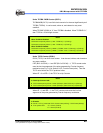
NOTE
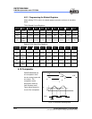
Details of the Fcarrier high time width and low time width are explained below:
Fcarrier = FT/ 2 { [1+decimal TCCC Counter value (IOC81)] * TCCC
Scale (IOCA0) }
High time width = { [1+decimal high time value (IOCA1)] * High time Scale
(IOCB1) } / FT
Low time width = { [1+decimal low time value (IOC91)] * Low time Scale
(IOCB1) } / FT
Where FT is the system clock FT=Fosc/1 (CLK=2)
FT=Fosc/2 (CLK=4)