


EM78P259N/260N
8-Bit Microprocessor with OTP ROM
Product Specification (V1.2) 05.18.2007
• 17
(This specification is subject to change without further notice)
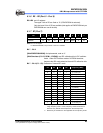
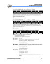
Bit 1 (TCCATS): TCCA signal source
0 =: internal instruction cycle clock. P61 is a bi-directional I/O pin.
1 = transit through the TCCA pin
Bit 0 (TCCATE): TCCA signal edge
0 = increment if transition from low to high takes place on the
TCCA pin
1 = increment if transition from high to low takes place on the
TCCA pin
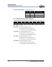
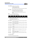
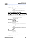
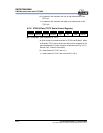
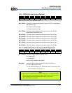
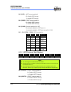
6.2.5 IOC90 (TCCB and TCCC Control Register)
Bit 7 Bit 6 Bit 5 Bit 4 Bit 3 Bit 2 Bit 1 Bit 0
TCCBHE TCCBEN TCCBTS TCCBTE – TCCCEN TCCCTS TCCCTE
Bit 7 (TCCBHE): Control bit is used to enable the most significant byte of counter
0 = Disable the most significant byte of TCCBH (default value)
TCCB is an 8-bit counter
1 = Enable the most significant byte of TCCBH
TCCB is a 16-bit counter
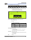
Bit 6 (TCCBEN): TCCB enable bit
0 = disable TCCB
1 = enable TCCB as a counter
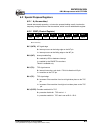
Bit 5 (TCCBTS) TCCB signal source
0 = internal instruction cycle clock. P62 is a bi-directional I/O pin.
1 = transit through the TCCB pin
Bit 4 (TCCBTE): TCCB signal edge
0 = increment if the transition from low to high takes place on the
TCCB pin
1 = increment if the transition from high to low takes place on the
TCCB pin
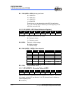
Bit 3: Not used.
Bit 2 (TCCCEN): TCCC enable bit
0 = disable TCCC
1 = enable TCCC as a counter
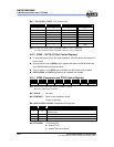
Bit 1 (TCCCTS) TCCC signal source
0 = internal instruction cycle clock. P63 is a bi-directional I/O pin.
1 = transit through the TCCC pin
Bit 0 (TCCCTE): TCCC signal edge