


EM78P259N/260N
8-Bit Microprocessor with OTP ROM
46 •
Product Specification (V1.2) 05.18.2007
(This specification is subject to change without further notice)
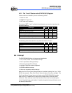
Bit 4 (ADRUN): ADC starts to RUN.
0 = reset on completion of the conversion. This bit cannot be reset
though software.
1 = an AD conversion is started. This bit can be set by software.
Bit 3 (ADPD): ADC Power-down mode.
0 = switch off the resistor reference to save power even
while the CPU is operating.
1 = ADC is operating
Bit 2: Not used
Bit 1 ~ Bit 0 (ADIS1 ~ ADIS0): Analog Input Select
00 = ADIN0/P50
01 = ADIN1/P51
10 = ADIN2/P52
11 = ADIN3/P53
These bits can only be changed when the ADIF bit and the ADRUN bit
are both LOW.
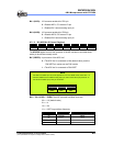
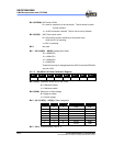
6.7.1.3 RA (ADOC: AD Offset Calibration Register)
Bit 7 Bit 6 Bit 5 Bit 4 Bit 3 Bit 2 Bit 1 Bit 0
CALI SIGN VOF[2] VOF[1] VOF[0] – – –
Bit 7 (CALI): Calibration enable bit for ADC offset
0 = Calibration disable
1 = Calibration enable
Bit 6 (SIGN): Polarity bit of offset voltage
0 = Negative voltage
1 = Positive voltage
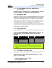
Bit 5 ~ Bit 3 (VOF[2] ~ VOF[0]): Offset voltage bits.
VOF[2] VOF[1] VOF[0] EM78P259N/260N ICE259N
0 0 0 0LSB 0LSB
0 0 1 2LSB 1LSB
0 1 0 4LSB 2LSB
0 1 1 6LSB 3LSB
1 0 0 8LSB 4LSB
1 0 1 10LSB 5LSB
1 1 0 12LSB 6LSB
1 1 1 14LSB 7LSB
Bit 2 ~ Bit 0: Unimplemented, read as ‘0’.