


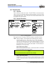

EM78P259N/260N
8-Bit Microprocessor with OTP ROM
Product Specification (V1.2) 05.18.2007
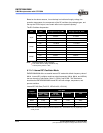
• 63
(This specification is subject to change without further notice)
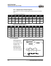
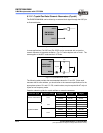
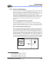
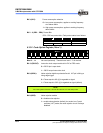
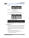
Circuit diagrams for serial and parallel modes Crystal/Resonator:
OSCI
EM78P259N
EM78P260N
C
7404
330 330
Crystal
7404 7404
Fig. 6-18 Serial Mode Crystal/Resonator Circuit Diagram
EM78P259N
EM78P260N
OSCI
7404
7404
C1
C2
10K4.7K
Vdd
10K
10K
Crystal
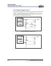
Fig. 6-19 Parallel Mode Crystal/Resonator Circuit Diagram
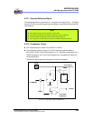
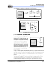
6.11.3 External RC Oscillator Mode
For some applications that do not require
precise timing calculation, the RC
oscillator (Fig. 6-20 right) could offer you
with effective cost savings. Nevertheless,
it should be noted that the frequency of
the RC oscillator is influenced by the
supply voltage, the values of the resistor
(Rext), the capacitor (Cext), and even by
the operation temperature. Moreover, the
frequency also changes slightly from one
chip to another due to manufacturing
process variation.
OSCI
EM78P259N
EM78P260N
Vcc
Rext
Cext
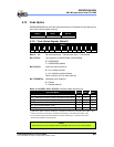
Fig. 6-20 External RC Oscillator Mode Circuit
In order to maintain a stable system frequency, the values of the Cext should be no less
than 20pF, and that of Rext should be no greater than 1MΩ. If the frequency cannot be
kept within this range, the frequency can be affected easily by noise, humidity, and
leakage.
The smaller the Rext in the RC oscillator is, the faster its frequency will be. On the
contrary, for very low Rext values, for instance, 1 KΩ, the oscillator will become
unstable because the NMOS cannot discharge the capacitance current correctly.