


EM78P259N/260N
8-Bit Microprocessor with OTP ROM
28 •
Product Specification (V1.2) 05.18.2007
(This specification is subject to change without further notice)
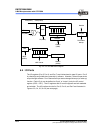
8-Bit counterWDT
Prescaler8 to 1 MUX
WDT Time out
WDTE
(IOCE0)
TCC Pin
MUX
1CLK (Fosc/1)
8-Bit Counter (IOCC1)
8 to 1 MUX
TE (CONT)
Data Bus
TCC overflow
interrupt
TS (CONT)
TCC (R1)
0
1
PSW2~0
(IOCE0)
Prescaler
PSR2~0
(CONT)
2 CLK (Fosc/2)
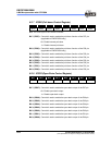
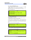
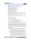
Fig. 6-2 TCC and WDT Block Diagram
6.4 I/O Ports
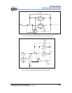
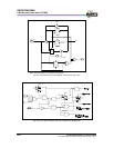
The I/O registers (Port 5, Port 6, and Port 7) are bi-directional tri-state I/O ports. Port 5
is pulled-high and pulled-down internally by software. Likewise, P6 has its open-drain
output through software. Port 5 features an input status changed interrupt (or wake-up)
function. Each I/O pin can be defined as "input" or "output" pin by the I/O control
register (IOC5 ~ IOC7). The I/O registers and I/O control registers are both readable
and writable. The I/O interface circuits for Port 5, Port 6, and Port7 are illustrated in
Figures 6-3, 6-4, 6-5, & 6-6 (see next page).