


EM78P259N/260N
8-Bit Microprocessor with OTP ROM
Product Specification (V1.2) 05.18.2007
• 61
(This specification is subject to change without further notice)
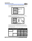
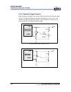
6.11 Oscillator
6.11.1 Oscillator Modes
The EM78P259N/260N can be operated in four different oscillator modes, such as High
Crystal oscillator mode (HXT), Low Crystal oscillator mode (LXT), External RC
oscillator mode (ERC), and RC oscillator mode with Internal RC oscillator mode (IRC).
You can select one of them by programming the OSC2, OCS1, and OSC0 in the Code
Option register.
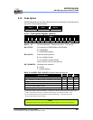
The Oscillator modes defined by OSC2, OCS1, and OSC0 are described below.
Oscillator Modes OSC2 OSC1 OSC0
ERC
1
(External RC oscillator mode); P70/OSCO acts as P70 0 0 0
ERC
1
(External RC oscillator mode); P70/OSCO acts as OSCO 0 0 1
IRC
2
(Internal RC oscillator mode); P70/OSCO acts as P70 0 1 0
IRC
2
(Internal RC oscillator mode); P70/OSCO acts as OSCO 0 1 1
LXT
3
(Low Crystal oscillator mode) 1 1 0
HXT
3
High Crystal oscillator mode) (default) 1 1 1
1
In ERC mode, OSCI is used as oscillator pin. OSCO/P70 is defined by code option Word 0 Bit 6 ~ Bit 4.
2
In IRC mode, P55 is normal I/O pin. OSCO/P70 is defined by code option Word 0 Bit 6 ~ Bit 4.
3
In LXT and HXT modes; OSCI and OSCO are used as oscillator pins. These pins cannot and should not
be defined as normal I/O pins.
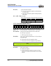
NOTE
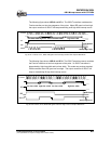
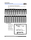
The transient point of the system frequency between HXT and LXY is around 400kHz.
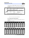
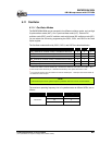
The maximum operating frequency limit of crystal/resonator at different VDDs, are as
follows:
Conditions VDD Max. Freq. (MHz)
2.3 4
3.0 8
Two clocks
5.0 20