


EM78P259N/260N
8-Bit Microprocessor with OTP ROM
76 •
Product Specification (V1.2) 05.18.2007
(This specification is subject to change without further notice)
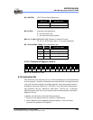
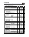
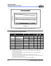
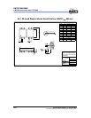
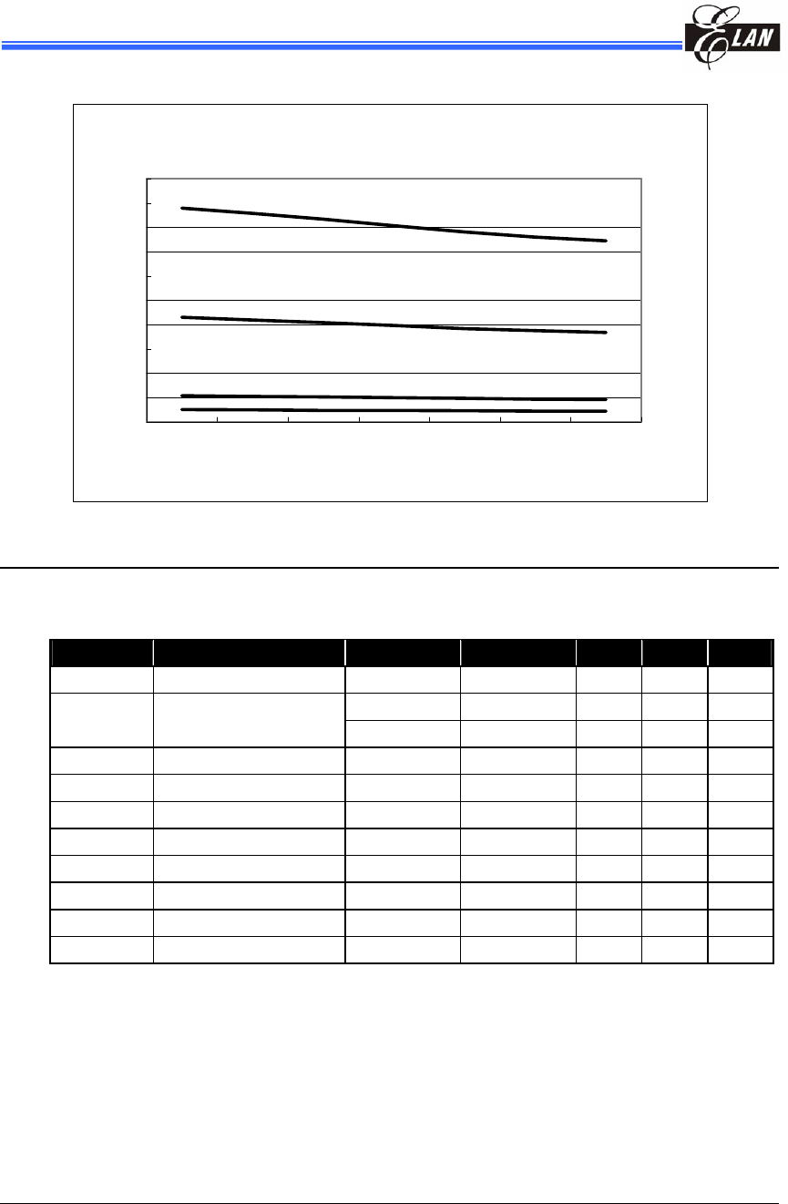
IRC OSC Frequency (VDD=5V)
0
1
2
3
4
5
6
7
8
9
10
-40-200 25507085
Temper at ur e (℃ )
Frequency (M Hz)
Fig. 8-2 Internal RC OSC Frequency vs. Temperature, VDD=5V
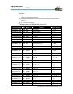
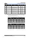
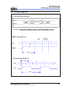
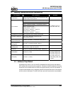
9 AC Electrical Characteristic
Ta=25
°
C, VDD=5V±5%, VSS=0V
Symbol Parameter Conditions Min Typ Max Unit
Dclk Input CLK duty cycle
45 50 55 %
Crystal type 100 DC ns
Tins
Instruction cycle time
(CLKS="0")
RC type 500 DC ns
Ttcc TCC input period
(Tins+20)/N* ns
Tdrh Device reset hold time
Ta = 25°C 11.3 16.2 21.6 ms
Trst /RESET pulse width
Ta = 25°C 2000 ns
Twdt Watchdog timer period
Ta = 25°C 11.3 16.2 21.6 ms
Tset Input pin setup time
0 ns
Thold Input pin hold time
15 20 25 ns
Tdelay Output pin delay time
Cload=20pF 45 50 55 ns
Tdrc ERC delay time
Ta = 25°C 1 3 5 ns
Note: 1. N = selected prescaler ratio
2. Twdt1: The Option Word1 (WDTPS) is used to define the oscillator set-up time. WDT timeout length is
the same as set-up time (18ms).
3. Twdt2: The Option Word1 (WDTPS) is used to define the oscillator set-up time. WDT timeout length is
the same as set-up time (4.5ms).
4. These parameters are hypothetical (not tested) and are provided for design reference only.
5. Data under minimum, typical, & maximum (Min, Typ, & Max) columns are based on hypothetical results at 25
°
C.
These data are for design reference use only.
6. The Watchdog timer duration is determined by Code Option Word1 (WDTPS).