


EM78P259N/260N
8-Bit Microprocessor with OTP ROM
Product Specification (V1.2) 05.18.2007
• 13
(This specification is subject to change without further notice)
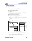
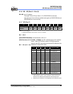
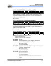
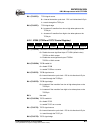
6.1.12 RC (ADDATA1H: Converted Value of ADC)
Bit 7 Bit 6 Bit 5 Bit 4 Bit 3 Bit 2 Bit 1 Bit 0
“0” “0” “0” “0” AD11 AD10 AD9 AD8
When AD conversion is completed, the result is loaded into the ADDATA1H. The
ADRUN bit is cleared, and the ADIF (see Section 6.1.14, RE (Interrupt Status 2 &
Wake-up Control Register)) is set.
RC is read only
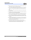
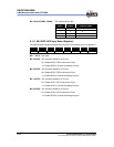
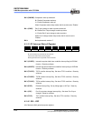
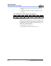
6.1.13 RD (ADDATA1L: Converted Value of ADC)
Bit 7 Bit 6 Bit 5 Bit 4 Bit 3 Bit 2 Bit 1 Bit 0
AD7 AD6 AD5 AD4 AD3 AD2 AD1 AD0
When AD conversion is completed, the result is loaded into the ADDATA1L. The
ADRUN bit is cleared, and the ADIF (see Section 6.1.14, RE (Interrupt Status 2 &
Wake-up Control Register)) is set.
RD is read only
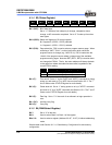
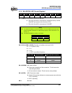
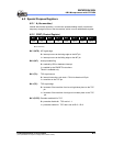
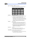
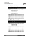
6.1.14 RE (Interrupt Status 2 & Wake-up Control Register)
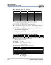
Bit 7 Bit 6 Bit 5 Bit 4 Bit 3 Bit 2 Bit 1 Bit 0
– – ADIF CMPIF ADWE CMPWE ICWE -
Note: RE <5, 4> can be cleared by instruction but cannot be set
IOCE0 is the interrupt mask register
Reading RE will result to "logic AND" of RE and IOCE0
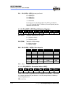
Bit 7 & Bit 6: Not used
Bit 5 (ADIF): Interrupt flag for analog to digital conversion. Set when AD
conversion is completed. Reset by software
0 = no interrupt occurs
1 = with interrupt request
Bit 4 (CMPIF): Comparator interrupt flag. Set when a change occurs in the output of
Comparator. Reset by software.
0 = no interrupt occurs
1 = with interrupt request
Bit 3 (ADWE): ADC wake-up enable bit
0 = Disable ADC wake-up
1 = Enable ADC wake-up
When AD Conversion enters sleep mode, this bit must be set to
“Enable“.