


EM78P259N/260N
8-Bit Microprocessor with OTP ROM
Product Specification (V1.2) 05.18.2007
• 41
(This specification is subject to change without further notice)
6.5.2 The T and P Status under STATUS (R3) Register
A reset condition is initiated by one of the following events:
1. Power-on reset
2. /RESET pin input "low"
3. WDT time-out (if enabled).
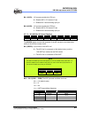
The values of RST, T, and P as listed in the table below, are used to check how the
processor wakes up.
Reset Type RST T P
Power-on 0 1 1
/RESET during Operating mode 0 *P *P
/RESET wake-up during Sleep mode 0 1 0
WDT during Operating mode 0 0 1
WDT wake-up during Sleep mode 0 0 0
Wake-up on pin change during Sleep mode 1 1 0
*P: Previous status before reset
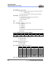
The following shows the events that may affect the status of T and P.
Event RST T P
Power-on 0 1 1
WDTC instruction *P 1 1
WDT time-out 0 0 *P
SLEP instruction *P 1 0
Wake-up on pin changed during Sleep mode 1 1 0
*P: Previous value before reset
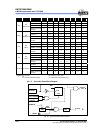
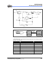
6.6 Interrupt
The EM78P259N/260N has six interrupts as listed below:
1. TCC, TCCA, TCCB, TCCC overflow interrupt
2. Port 5 Input Status Change Interrupt
3. External interrupt [(P60, /INT) pin]
4. Analog to Digital conversion completed
5. IR/PWM underflow interrupt
6. When the comparators status changes
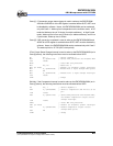
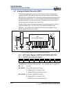
Before the Port 5 Input Status Change Interrupt is enabled, reading Port 5 (e.g. "MOV
R5,R5") is necessary. Each Port 5 pin will have this feature if its status changes. The
Port 5 Input Status Change Interrupt will wake-up the EM78P259N/260N from the
sleep mode if it is enabled prior to going into the sleep mode by executing SLEP
instruction. When wake-up occurs, the controller will continue to execute program
in-line if the global interrupt is disabled. If enabled, the global interrupt will branch out to
the interrupt Vector 006H.