


EM78P259N/260N
8-Bit Microprocessor with OTP ROM
42 •
Product Specification (V1.2) 05.18.2007
(This specification is subject to change without further notice)
The external interrupt has an on-chip digital noise rejection circuit. Input pulse less
than 8 system clock time is eliminated as noise. However, in Low Crystal oscillator
(LXT) mode the noise rejection circuit is disabled. Edge selection is possible with INTE
of CONT. When an interrupt is generated by the External interrupt (when enabled), the
next instruction will be fetched from Address 003H. Refer to Word 1 Bits 9 & 8, Section
6.14.2, Code Option Register (Word 1) for digital noise rejection definition
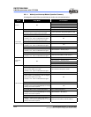
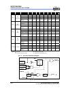
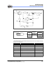
RF and RE are the interrupt status register that records the interrupt requests in the
relative flags/bits. IOCF0 and IOCE0 are interrupt mask registers. The global interrupt
is enabled by the ENI instruction and is disabled by the DISI instruction. Once in the
interrupt service routine, the source of an interrupt can be determined by polling the flag
bits in RF. The interrupt flag bit must be cleared by instructions before leaving the
interrupt service routine to avoid recursive interrupts.
The flag (except for the ICIF bit) in the Interrupt Status Register (RF) is set regardless of
the ENI execution. Note that the result of RF will be the logic AND of RF and IOCF0
(refer to figure below). The RETI instruction ends the interrupt routine and enables the
global interrupt (the ENI execution).
When an interrupt is generated by the Timer clock/counter (if enabled), the next
instruction will be fetched from Address 009, 018, 01B, and 01EH (TCC, TCCA, TCCB,
and TCCC respectively).
When an interrupt generated by the AD conversion is completed (if enabled), the next
instruction will be fetched from Address 00CH.
When an interrupt is generated by the High time / Low time down counter underflow (if
enabled), the next instruction will be fetched from Address 012 and 015H (High time
and Low time respectively).
When an interrupt is generated by the Comparators (if enabled), the next instruction will
be fetched from Address 00FH (Comparator interrupt).
Before the interrupt subroutine is executed, the contents of ACC and the R3 and R4
registers will be saved by the hardware. If another interrupt occurs, the ACC, R3, and
R4 will be replaced by the new interrupt. After the interrupt service routine is completed,
the ACC, R3, and R4 registers are restored.