


EM78P259N/260N
8-Bit Microprocessor with OTP ROM
24 •
Product Specification (V1.2) 05.18.2007
(This specification is subject to change without further notice)
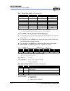
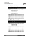
6.2.14 IOC71 (TCCBH/MSB Counter)
The IOC71 (TCCBH) is an 8-bit clock counter for the most significant byte of TCCBX
(TCCBH). It can be read, written, and cleared on any reset condition.
When TCCBHE (IOC90) is “0,” then TCCBH is disabled. When TCCBHE is”1,” then
TCCB is a 16-bit length counter.
NOTE
When TCCBH is Disabled:
■ TCCB time-out period [1/Fosc x ( 256 - TCCB cnt ) x 1(CLK=2)]
■ TCCB time-out period [1/Fosc x ( 256 - TCCB cnt ) x 2(CLK=4)]
When TCCBH is Enabled:
■ TCCB time-out period {1/Fosc x [ 65536 - (TCCBH * 256 + TCCB cnt)] x 1(CLK=2)}
■ TCCB time-out period {1/Fosc x [ 65536 - (TCCBH * 256 + TCCB cnt)] x 2(CLK=4)}
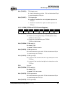
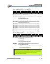
6.2.15 IOC81 (TCCC Counter)
The IOC81 (TCCC) is an 8-bit clock counter that can be extended to 16-bit counter.
It can be read, written, and cleared on any reset condition.
If HF (Bit 2 of IOCA0) = 1 and IRE (Bit 3 of IOCA0) = 1, TCCC counter scale uses the
low time segments of the pulse generated by Fcarrier frequency modulation (see Fig.
6-12 in Section 6.8.2, Function Description). Then TCCC value will be TCCC predict
value.
When HP = 0 or IRE = 0, the TCCC is an Up Counter.
NOTE
In TCCC Up Counter mode:
■ TCCC time-out period [1/Fosc x scaler (IOCA0) x (256-TCCC cnt) x 1(CLK=2)]
■ TCCC time-out period [1/Fosc x scaler (IOCA0) x (256-TCCC cnt) x 2(CLK=4)]
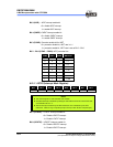
When HP = 1 and IRE = 1, TCCC counter scale uses the low time segments of the
pulse generated by Fcarrier frequency modulation.
NOTE
In IR mode:
■ Fcarrier = FT/ 2 { [1+decimal TCCC Counter value (IOC81)] * TCCC Scale
(IOCA0) }
■ FT is system clock: FT = Fosc/1 (CLK=2)
FT = Fosc/2 (CLK=4)