


EM78P259N/260N
8-Bit Microprocessor with OTP ROM
22 •
Product Specification (V1.2) 05.18.2007
(This specification is subject to change without further notice)
Bit 5 (ADIE): ADIF interrupt enable bit
0 = disable ADIF interrupt
1 = enable ADIF interrupt
Bit 4 (CMPIE): CMPIF interrupt enable bit.
0 = disable CMPIF interrupt
1 = enable CMPIF interrupt
Bit 3 (PSWE): Prescaler enable bit for WDT
0 = prescaler disable bit, WDT rate is 1:1
1 = prescaler enable bit, WDT rate is set as Bit 2 ~ Bit 0
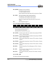
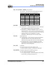
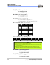
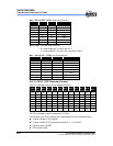
Bit 2 ~ Bit 0 (PSW2 ~ PSW0): WDT prescaler bits
PSW2 PSW1 PSW0 WDT Rate
0 0 0 1:2
0 0 1 1:4
0 1 0 1:8
0 1 1 1:16
1 0 0 1:32
1 0 1 1:64
1 1 0 1:128
1 1 1 1:256
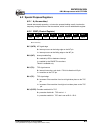
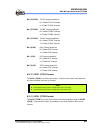
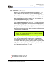
6.2.11 IOCF0 (Interrupt Mask Register)
Bit 7 Bit 6 Bit 5 Bit 4 Bit 3 Bit 2 Bit 1 Bit 0
LPWTIE HPWTIE TCCCIE TCCBIE TCCAIE EXIE ICIE TCIE
NOTE
■ The IOCF0 register is both readable and writable
■ Individual interrupt is enabled by setting its associated control bit in the IOCF0 and
in IOCE0 Bit 4 & 5 to "1".
■ Global interrupt is enabled by the ENI instruction and is disabled by the DISI
instruction. Refer to Fig. 6-8 (Interrupt Input Circuit) under Section 6.6 (Interrupt).
Bit 7 (LPWTIE): LPWTIF interrupt enable bit
0 = Disable LPWTIF interrupt
1 = Enable LPWTIF interrupt
Bit 6 (HPWTIE): HPWTIF interrupt enable bit
0 = Disable HPWTIF interrupt
1 = Enable HPWTIF interrupt