


EM78P259N/260N
8-Bit Microprocessor with OTP ROM
Product Specification (V1.2) 05.18.2007
• 49
(This specification is subject to change without further notice)
NOTE
In order to obtain accurate values, it is necessary to avoid any data transition on the
I/O pins during AD conversion.
6.7.6.2 Sample Demo Programs
A. Define a General Register
R_0 == 0 ; Indirect addressing register
PSW == 3 ; Status register
PORT5 == 5
PORT6 == 6
R_E== 0XE ; Interrupt status register
B. Define a Control Register
IOC50 == 0X5 ; Control Register of Port 5
IOC60 == 0X6 ; Control Register of Port 6
C_INT== 0XF ; Interrupt Control Register
C. ADC Control Register
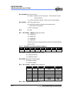
ADDATA == 0xB ; The contents are the results of ADC
AISR == 0x08 ; ADC input select register
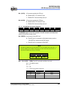
ADCON == 0x9 ; 7 6 5 4 3 2 1 0
; VREFS CKR1 CKR0 ADRUN ADPD ADIS2 ADIS1 ADIS0
D. Define Bits in ADCON
ADRUN == 0x4 ; ADC is executed as the bit is set
ADPD == 0x3 ; Power Mode of ADC
E. Program Starts
ORG 0 ; Initial address
JMP INITIAL ;
ORG 0x0C ; Interrupt vector
JMP CLRRE
;
;
;(User program section)
;
;
CLRRE:
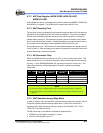
MOV A,RE
AND A, @0BXX0XXXXX ; To clear the ADIF bit, “X” by application
MOV RE,A
BS ADCON, ADRUN ; To start to execute the next AD conversion
if necessary