


EM78P259N/260N
8-Bit Microprocessor with OTP ROM
68 •
Product Specification (V1.2) 05.18.2007
(This specification is subject to change without further notice)
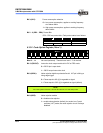
Bit 3 (HLP): Power consumption selection
0 = Low power consumption, applies to working frequency
at or below 4MHz
1 = High power consumption, applies to working frequency
above 4MHz
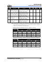
Bit 2 ~ 0 (PR2 ~ PR0): Protect Bits
PR2 ~ PR0 are protect bits. Each protect status is as follows:
PR2 PR1 PR0 Protect
Others Enable
1 1 1 Disable
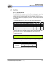
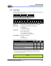
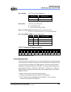
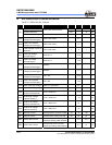
6.13.2 Code Option Register (Word 1)
Word 1
Bit 12 Bit 11 Bit 10 Bit 9 Bit 8 Bit 7 Bit 6 Bit 5 Bit 4 Bit 3 Bit 2 Bit 1 Bit 0
- - RCOUT NRHL NRE WDTPS CYES C3 C2 C1 C0 RCM1 RCM0
Bits 12 ~ 11: Not used (reserved). These bits are set to “1” all the time
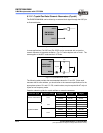
Bit 10 (RCOUT): Instruction clock output enable bit in IRC or ERC mode
0 = OSCO pin is open drain
1 = OSCO output instruction clock
Bit 9 (NRHL): Noise rejection high/low pulses define bit. INT pin is falling or
rising edge trigger
0 = Pulses equal to 8/fc [s] is regarded as signal
1 = Pulses equal to 32/fc [s] is regarded as signal (default)
NOTE
The noise rejection function is turned off under the LXT and sleep mode.
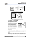
Bit 8 (NRE): Noise rejection enable
0 = disable noise rejection
1 = enable noise rejection (default), but under Low Crystal
oscillator (LXT) mode, the noise rejection circuit is always
disabled.