


EM78P259N/260N
8-Bit Microprocessor with OTP ROM
40 •
Product Specification (V1.2) 05.18.2007
(This specification is subject to change without further notice)
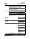
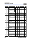
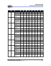
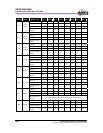
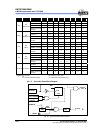
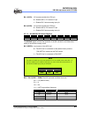
Address Name Reset Type Bit 7 Bit 6 Bit 5 Bit 4 Bit 3 Bit 2 Bit 1 Bit 0
Bit Name “0” “0” “0” “0” AD11 AD10 AD9 AD8
Power-on 0 0 0 0 U U U U
/RESET and WDT 0 0 0 0 U U U U
0XC
RC
(ADDATA1H)
Wake-up from Pin
Change
0 0 0 0 P P P P
Bit Name AD7 AD6 AD5 AD4 AD3 AD2 AD1 AD0
Power-on U U U U U U U U
/RESET and WDT U U U U U U U U
0XD
RD
(ADDATA1L0)
Wake-up from Pin
Change
P P P P P P P P
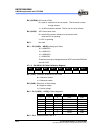
Bit Name –- – ADIF CMPIF ADWE CMPWE ICWE –
Power-un 0 0 0 0 0 0 0 0
/RESET and WDT 0 0 0 0 0 0 0 0
0xE
RE
(ISR2)
Wake-up from Pin
Change
P P P P P P P P
Bit Name LPWTIF HPWTIF TCCCIF TCCBIF TCCAIF EXIF ICIF TCIF
Power-on 0 0 0 0 0 0 0 0
/RESET and WDT 0 0 0 0 0 0 0 0
0xF
RF
(ISR1)
Wake-up from Pin
Change
P P P P P P P P
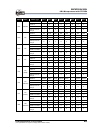
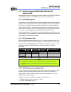
Bit Name – – – – – – – –
Power-on U U U U U U U U
/RESET and WDT P P P P P P P P
0x10~0x3F R10~R3F
Wake-up from Pin
Change
P P P P P P P P
Legend: ×: Not used U: Unknown or don’t care
P: Previous value before reset
t: Check table under Section 6.5.2.
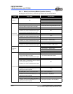
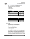
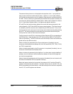
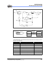
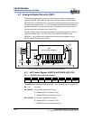
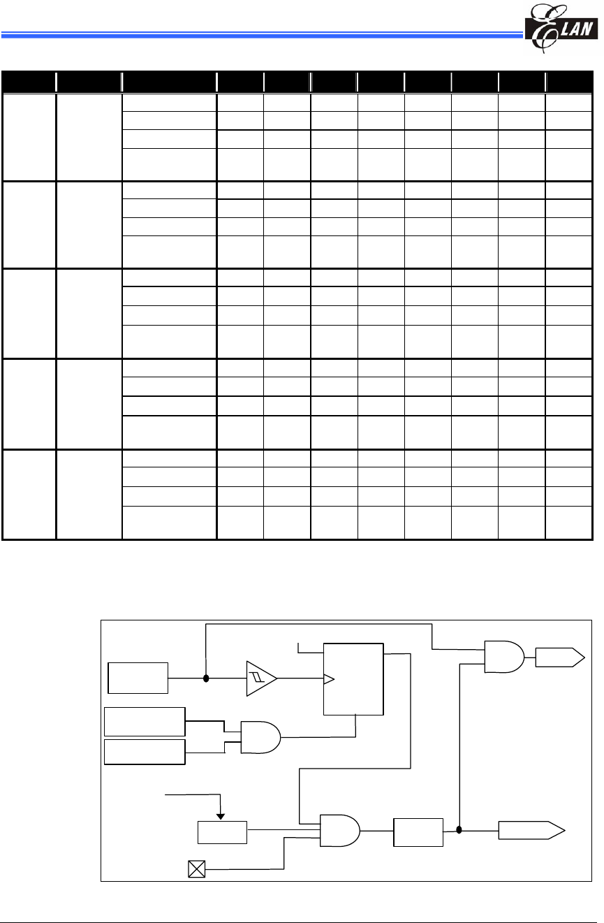
6.5.1.3 Controller Reset Block Diagram
WDT
Timeout
Oscillator
D Q
CLK
CLR
WDT
VDD
Setup
time
Reset
CLK
/RESET
Power-on Reset
Voltage
Detector
ENWDTB
Fig. 6-7 Controller Reset Block Diagram