


EM78P259N/260N
8-Bit Microprocessor with OTP ROM
Product Specification (V1.2) 05.18.2007
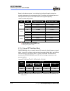
• 59
(This specification is subject to change without further notice)
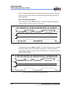
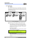
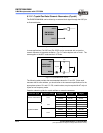
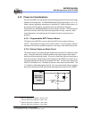
6.10.1 External Reference Signal
The analog signal that is presented at Cin– compares to the signal at Cin+. The digital
output (CO) of the comparator is adjusted accordingly by taking the following notes into
considerations:
NOTE
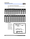
■ The reference signal must be between Vss and Vdd.
■ The reference voltage can be applied to either pin of the comparator.
■ Threshold detector applications may be of the same reference.
■ The comparator can operate from the same or different reference sources.
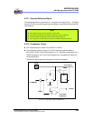
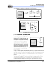
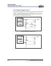
6.10.2 Comparator Output
The compared result is stored in the CMPOUT of IOC80.
The comparator outputs are sent to CO (P64) through programming Bit 4 &
Bit 3<COS1, COS0> of the IOC80 register to <1,0>. See table under Section 6.2.4,
IOC80 (Comparator and TCCA Control Registers) for Comparator/OP select bits
function description.
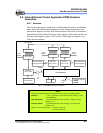
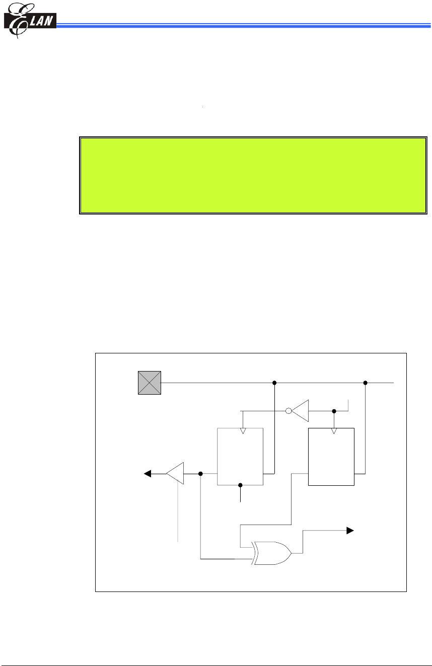
The following figure shows the Comparator Output block diagram.
Q
Q
ENEN
D
D
To C0
To CPIF
To CMPOUT
CMRD
CMRD
From other
comparator
RESET
From OP I/O
Fig. 6-15 Comparator Output Configuration