


Intel 8255x 10/100 Mbps Ethernet Controller Family Open Source Software Developer Manual 99
Host Software Interface
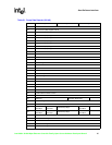
During Phase 1, the linear feedback shift register (LFSR), exponential backoff time-out, slot time,
and collision counters are checked. The test is performed in the following manner:
1. All counters and shift registers are reset simultaneously.
2. The unit starts counting and shifting the registers.
3. The exponential backoff shift register reaches all ones.
4. The unit checks the exponential backoff shift register for all ones when the LFSR content is all
ones in its 10 least significant bits.
5. The unit stops counting when the LFSR (30 bits) reaches a specific state, and the exponential
backoff counter (10 bits) wraps from all ones to all zeroes. Simultaneously, the slot time
counter switches from 01111111111 to 10000000000, and the collision counter (4 bits) wraps
from all ones to all zeroes.
6. Phase 1 is successful if the 10 least significant bits (when applicable) of all four counters are
all zero.
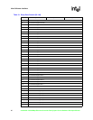
During Phase 2, the test is performed in the following steps:
1. The exponential backoff shift register, LFSR, and all counters are reset.
2. The exponential backoff logic is temporarily configured accordingly:
a. SLOT-TIME = 3h
b. LIN-PRIO = 6h
c. EXP-PRIO = 3h
d. BOF-MET = 0h
3. Transmission and collisions are emulated internally.
4. If the most significant bit of exponential backoff shift register is 0, then step 3 is repeated.
If Step 4 is successful, then a passed status is returned; otherwise, a failed status is returned.
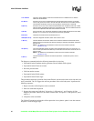
6.4.3 Receive Operation
6.4.3.1 Receive Frame Area
The 8255x supports the concept of a receive frame area (RFA). The RFA is the list of free receive
resources and consists of Receive Frame Descriptors (RFDs). The RFDs contain data buffers
capable of holding maximum Ethernet size packets immediately following the RFD header. This
constitutes the simplified memory model. Each receive frame is described by one RFD.
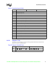
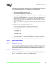
6.4.3.1.1 Simplified RFA Structure
In the simplified RFA structure, the data portion of the received frame (including the Ethernet
header) is part of the RFD and is located in contiguous memory immediately after the size field in
the RFD. The simplified memory structure is shown in the figure below.