


Intel 8255x 10/100 Mbps Ethernet Controller Family Open Source Software Developer Manual 91
Host Software Interface
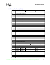
The load microcode command instructs the device to download microcode data from host memory
into its internal microcode RAM. The microcode data is organized as a 64-Dword memory block
that is appended to a standard command block header. The device starts execution of downloaded
microcode immediately following the successful completion of the load microcode command. The
device continues executing the downloaded microcode until the device is reset through its
hardware or software reset mechanisms.
Note: Documentation for developing new microcode patches for the Intel
®
Fast Ethernet controllers is
beyond the scope of this manual.
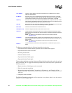
6.4.2.7 Dump (110b)
This command causes the contents of various device registers to be placed in a memory area
specified by the user. It is supplied as a self diagnostic tool and provides registers of interest to the
user. The format of the dump command is shown below.
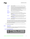
Link Address
This is the 32-bit address of the next command block. It is added to the CU base to
obtain the actual address.
EL (Bit 31)
If this bit is set to one, it indicates that this command block is the last one on the CBL.
The CU will go from the active to the idle state after the execution of the CB is finished.
This transition will always cause an interrupt with the CNA/CI bit set in the SCB.
S (Bit 30)
If this bit is set to one, the CU will be suspended after the completion of this CB. A CNA
interrupt will be generated if the device is configured for this. The CU transitions from the
active to the suspended state after the execution of the CB.
I (Bit 29)
If the I bit is set to one, the device generates an interrupt after the execution of the CB is
finished. If I is not set to one, the CX interrupt will not be generated.
Bits 28:19 These bits are reserved and should all be set to 0.
CMD (Bits 18:16) This is the load microcode command, which has a value of 101b.
C (Bit 15)
This bit indicates the execution status of the command. Software should reset this bit
before issuing the command to the device. Following a command completion, the device
sets it to one.
NOTE: The difference in the definition of the C bit for the transmit command
(Section 6.4.2.5).
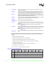
OK (Bit 13)
The OK bit indicates that the command was executed without error. If it equals one, no
error occurred (command executed OK). If the OK bit is zero and the C bit is set, then an
error occurred.
NOTE: The difference in the definition of the C bit for the transmit command
(Section 6.4.2.5).
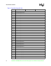
Microcode Data
This field contains the 64 Dwords of microcode data downloaded to the device. This data
patches the device’s hard-coded microcode, which allows the behavior of the device to
be altered or adapted.
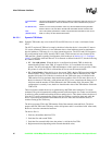
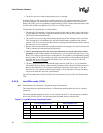
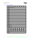
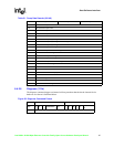
Figure 22. Dump Command Format
Offset Command Word Bits 31:16 Status Word Bits 15:0
00h EL S I 0000000000 110 C X OK XXXXXXXXXXXXX
04h Link Address (A31:A0)
08h Buffer Address