


100 Intel 8255x 10/100 Mbps Ethernet Controller Family Open Source Software Developer Manual
Host Software Interface
6.4.3.1.2 Receive Frame Descriptor Format
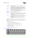
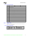
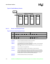
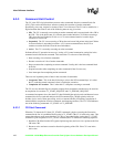
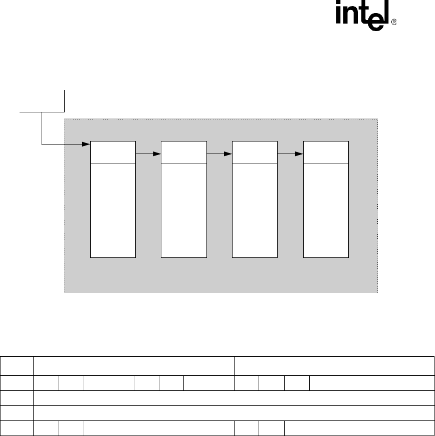
Figure 24. Simplified Memory Structure
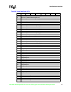
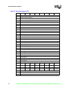
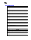
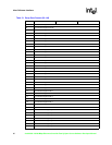
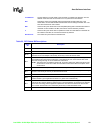
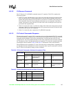
Figure 25. Receive Frame Descriptor Format
Offset Command Word Bits 31:16 Status Word Bits 15:0
00h EL S 000000000 H SF 000 C 0 OK Status Bits
04h Link Address (A31:A0)
08h Reserved
0Ch 0 0 Size EOF F Actual Count
EL (Bit 31) The EL bit indicates that this RFD is the last one in the RFA.
S (Bit 30) The S bit suspends the RU after receiving the frame.
H (Bit 20)
The H bit indicates if the current RFD is a header RFD. If it equals 1, the current RFD is
a header RFD, and if it is 0, it is not a header RFD.
NOTE: If a load HDS command was not previously issued, the device disregards this
bit.
SF (Bit 19) The SF bit equals 0 for simplified mode.
C (Bit 15) This bit indicates the completion of frame reception. It is set by the device.
OK (Bit 13)
The OK bit indicates whether the frame was received without any errors and stored in
memory. If the last frame was received with sufficient memory space, the OK bit will be
set, even if it was the last RFD in the RFA with the EL bit set. After receiving the frame,
the device enters the no resource condition, generates an RNR interrupt, and starts
discarding frames until the RU is restarted with sufficient resources.
Status Bits
(Bits 12:0)
This field contains the results of the receive operation:
RFD
Sequential
Data Buffer
SCB
RFD
Sequential
Data Buffer
RFD
Sequential
Data Buffer
RFD
Sequential
Data Buffer
RECEIVE FRAME AREA