


126 10/100 Mbps Ethernet Controller Family Open Source Software Developer Manual
Physical Layer Interface
7.3.3 Clock Synthesis Test and Control Register: Register 18
7.3.4 100BASE-TX Receive False Carrier Counter: Register 19
7.3.5 100Base-TX Receive Disconnect Counter: Register 20
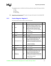
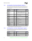
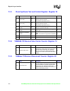
Bit Name R / W Description Default
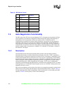
15 Clock Timing
RW
SC
Clock Synthesizer Shift command. One shot
signaling YS10ACLK domain.
Can be active only when bit 14 is ‘0
14 Clock Timing
RW
SC
Clock Synthesizer load command. One shot
signaling YS10ACLK domain.
Can be active only when bit 15 is ‘0
13
Break Down Timer
Enable
RW
Logic 1 enables manipulate Break Down counter
with phya1, phya4 and test high.
12
Equalizer Probe Mode
Enable
Logic 1 enables the Equalizer output through the
Speed LED.
0
11
10BASE-T Probe Mode
Enable
RW
1 = Enable 10BASE-T dig outputs through the
LEDs
NOTE: This function is only present on the 82559.
0
10:8 Reserved These bits are reserved. 0
4:0 PHY Address RO This field contains the PHY address. 00001
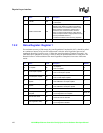
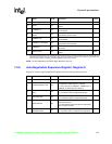
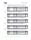
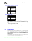
Bit Name R / W Description Default
15:0 Receive False Carrier
RO
SC
This register contains a 16-bit counter for false
carrier events. A false carrier event occurs when a
frame that does not start with “JK” is detected.
When the counter is full, additional false carrier
events are not counted. This counter is self-clearing
on read.
0
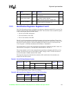
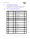
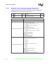
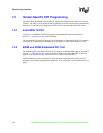
Bit Name R / W Description Default
15:0 Disconnect Event
RO
SC
This register contains a 16-bit counter for
disconnect events. The counter is incremented for
each frame detected in repeater mode that does
not start with a “JK.” When the counter is full,
additional disconnect events are not counted. This
counter is self-clearing on read.
0