


90 Intel 8255x 10/100 Mbps Ethernet Controller Family Open Source Software Developer Manual
Host Software Interface
• The device received a frame and generated a receive interrupt.
If neither of these events occurred, the controller generates a CNA interrupt when the CID time
interval has elapsed. The actual delay experienced may be longer than the CID value that was
loaded. The CID is given in a granularity of approximately 256 PCI clocks and the maximum value
is 8192 clocks (which corresponds to 8 to 256 µs in a 33 MHz system).
The delayed CNA interrupt flow is outlined below.
1. The delayed CNA interrupt is issued in the suspend or idle state. In other words, if the device
is in the suspend or idle state, raising the interrupt would be delayed by specified time in the
CID field of each command header.
2. The end of receive processing cancels the pending delayed CNA interrupt. It also causes the
CNA interrupt to be set simultaneously with the frame interrupt, regardless of the internal
counter value. This is based on the theory that any pending transmit cleanup would be done in
the context of a receive interrupt.
3. Resume and start commands cancel pending delayed CNA interrupts. This allows only the last
TCB of a chain to be interrupted (the rolling delay).
4. The CX interrupt (caused by the I bit) is not affected in any way by this mode or delay
parameter. It may be that regardless of anything else, we may want to interrupt on, say, every
third TX in a chain to return resources to the protocol. This would be accomplished by setting
the I bit in the TxCB. There would be no delay associated with an I-bit interrupt. Note that if I
and S bits are set in a TxCB and the CID field is set to a non-zero value, the CX & CNA
interrupts will not occur together
.
5. The delay specification is a 5-bit field and ranges between 8 and 256 µs, in 8 µs resolution.
The actual delay will only be within a certain percentage of the value specified (but never less
than the specified delay). The inaccuracy percentage is typically in the range of 10 to 20%.
However, in a few extreme conditions (for example, a lot of bad frames received), the delay
may be more than 20% above the specified delay.
The CNA interrupt delay (CID) field in the TCB is located in bits 28:24 of the first Dword of the
TCB.
6.4.2.6 Load Microcode (101b)
Note: Documentation for microcode is beyond the scope of this manual.
The load microcode command downloads a 64 Dword microcode patch to the device’s internal
microcode.
The microcode that operates on one device (for example, the 82557), will not operate on another
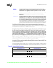
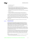
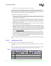
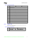
device (the 82558 or 82559). The load microcode command format is shown below:
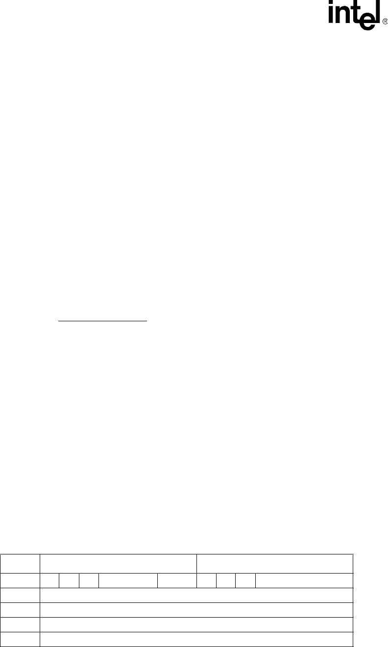
Figure 21. Load Microcode Command Format
Offset Command Word Bits 31:16 Status Word Bits 15:0
00h EL S I 0000000000 101 C X OK XXXXXXXXXXXXX
04h Link Address (A31:A0)
08h First Microcode Dword
260h 64th Microcode Dword