


Intel 8255x 10/100 Mbps Ethernet Controller Family Open Source Software Developer Manual 57
Host Software Interface
6.4 Shared Memory Structures
The 8255x shared memory structures consist of the Command Block List (CBL) and the Receive
Frame Area (RFA) and are controlled by the SCB portion of the CSR. The SCB is internal to the
device while the CBL and RFA reside in main system memory.
6.4.1 Action Commands and Operating Modes
In addition to SCB control commands, the device can be controlled with action commands. This
section lists all the action commands that can be a part of the CBL. Each command contains a
command field, status and control fields, a link to the next action command, and command specific
parameters. There are three basic types of action commands: device configuration and setup,
transmission, and diagnostics. Alignment requirements are detailed in Table 10, “Alignment
Requirements for 8255x Data Structures”.
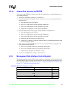
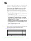
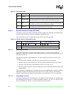
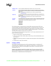
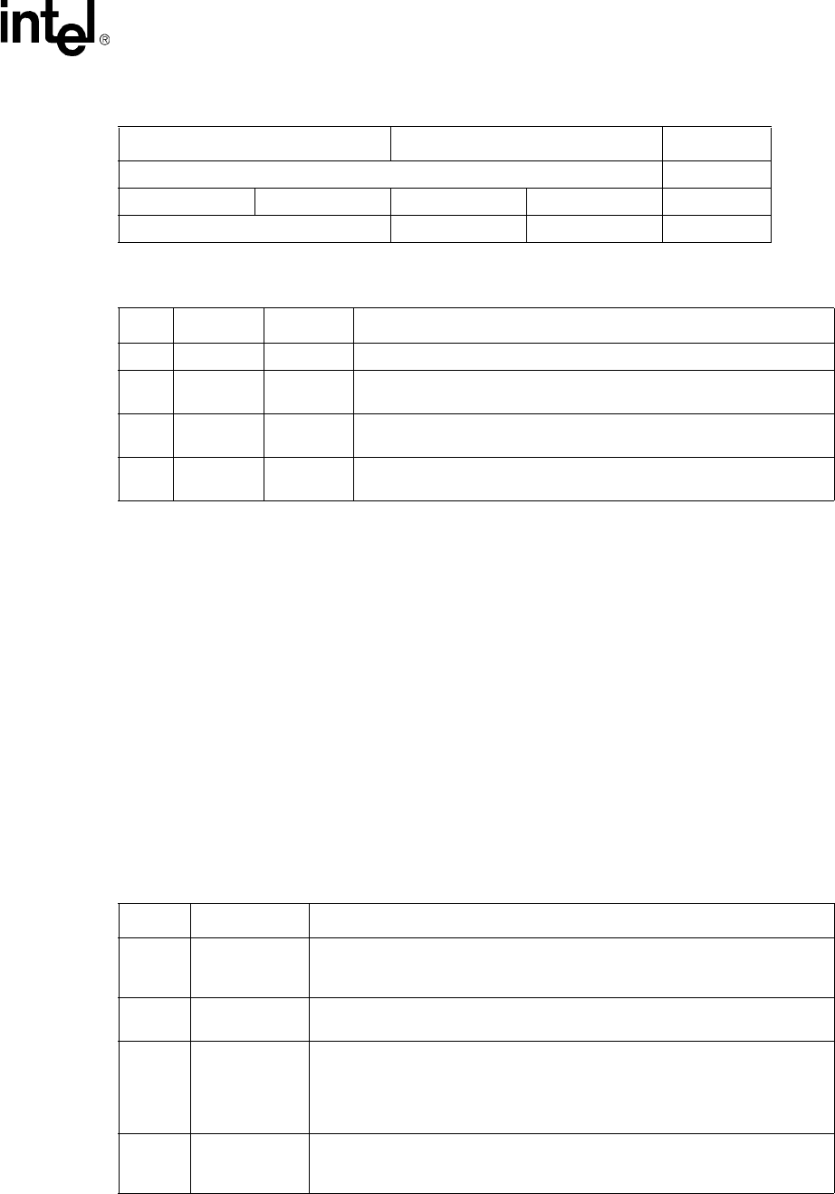
Early Receive Interrupt Receive Byte Count Register Base + 14h
PMDR FC Xon/Xoff FC Threshold Early Rx Int Base + 18h
Reserved General Status General Control Base + 1Ch
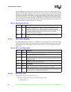
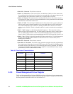
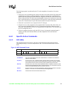
Table 36. General Status Register
Bits Operation Default Description
7:3 R 0 Reserved.
2R
HDX / FDX. This bit indicates duplex mode: 0 = half duplex (HDX) and 1
= full duplex (FDX).
1R
10 / 100 Mbps. This bit indicates the wire speed: 0 = 10 Mbps and 1 =
100 Mbps.
0R
Link Status Indication. This bit indicates the status of the link: 0 = link
down and 1 = link up.
Table 35. General Status Register Location
Upper Word (D31:D16) Lower Word (D15:D0) Offset
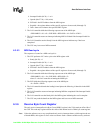
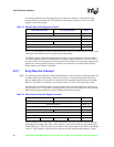
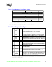
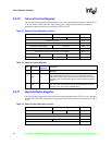
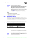
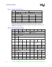
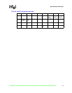
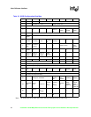
Table 37. Operation Codes
Opcode Name Description
000 NOP
This command results in no action by the device other than the normal
command processing such as fetching the command and decoding the
command field.
001
Individual
Address Setup
This command is used to load the device unique address. The unique address is
contained in the parameter field of the command.
010 Configure
The configure command is used to load the device with its operating
parameters. Upon reset, the device initializes to the IEEE 802.3 based
parameters, with the exception of choosing either the PHY interface mode (for
example, MII). If the user wishes to use any other values, the configure
command is used.
011
Multicast
Address Setup
This command allows the programmer to setup one or more multicast or
multiple individual addresses in the device. These addresses are located in the
parameter field of the command.