


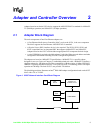


Intel 8255x 10/100 Mbps Ethernet Controller Family Open Source Software Developer Manual 11
PCI Interface 4
4.1 PCI Configuration Space
One of the most important functions for enabling superior configurability and ease of use is the
ability to relocate PCI devices in the address spaces. By default PCI devices support “Plug and
Play.” When the system is powered on, device independent software (usually the system BIOS)
determines present devices, builds an address map, and assigns non-conflicting resources to those
devices. The device independent software accomplishes this configuration task by writing to the
PCI configuration space of each individual PCI device.
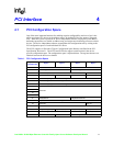
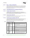
The 8255x supports 16 Dwords of Type 0 Configuration Space Header, as defined in the PCI
Specification, Revision 2.1. The 82259 and 82558 also support a small section in the device
specific configuration space. The configuration space is depicted below. The registers that are not
identical between the devices are shaded.
Table 1. PCI Configuration Space
Byte Offset
(hexadecimal)
Byte 3 Byte 2 Byte 1 Byte 0
0
Device ID Vendor ID
4 Status Register Command Register
8 Class Code (200000h) Revision ID
CBIST Header Type Latency Timer Cache Line Size
10 CSR Memory Mapped Base Address Register
14 CSR I/O Mapped Base Address Register
18
Flash Memory Mapped Base Address Register
1C
Reserved
20
24
28
2C
Subsystem ID Subsystem Vendor ID
30 Expansion ROM Base Address Register
34 Reserved Cap_Ptr
38 Reserved
3C Max_Latency (FFh) Min_Grant (FFh) Interrupt Pin (01h) Interrupt Line
DC
Power Management Capabilities Next Item Pointer Capability ID
E0 Reserved Data Power Management CSR