


12 Intel 8255x 10/100 Mbps Ethernet Controller Family Open Source Software Developer Manual
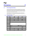
PCI Interface
4.1.1 Vendor ID (Offset 0)
This field identifies the device manufacturer. For the 82557 B-step this field equals 8086h. For the
82557 C-Step, 82558, and 82559, this field is automatically loaded from the EEPROM at power on
or upon the assertion of PCI reset. If the EEPROM is not present or invalid, this value defaults to
8086h.
4.1.2 Device ID (Offset 2)
This field uniquely identifies the device. For the 82557 B-step this field is 1229h. For the 82557 C-
Step, 82558, and 82559, this field is automatically loaded from the EEPROM at power on or upon
the assertion of PCI reset. If the EEPROM is not present or invalid, this value defaults to 1229h for
the 82558 and 82559. The 82559ER does not load the Device ID from the EEPROM and will
always equal 1209h.
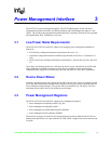
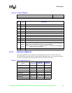
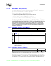
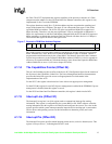
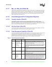
4.1.3 Command Register (Offset 4)
The Command Register provides control over the device’s ability to generate and respond to CPU
cycles. Its layout is shown below. The shaded bits are not used and are hard-wired to 0.
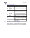
4.1.4 Status Register (Offset 6)
The Status Register is used to record status information for PCI bus related events. Its layout is
shown below. The shaded bits are not used and are hard-wired to 0.
Figure 2. Command Register
15 10 9 0
Reserved Command Bits
Bits
Initial
Value
Description
15:10 0 Reserved.
9 0 Fast back-to-back enable.
8 x SERR# enable.
7 0 Wait cycle enable.
6 x Parity error response
5 0 Palette snoop enable.
4x
Memory write and invalidate (MWI) enable.
NOTE: More information regarding the MWI command is located in Section 4.2.1,
“Memory Write and Invalidate”.
3 0 Special cycle monitoring.
2 x Mastering enable.
1 x Memory access enable.
0 x I/O access enable.