


Intel 8255x 10/100 Mbps Ethernet Controller Family Open Source Software Developer Manual 79
Host Software Interface
byte (7Eh) will be transmitted to pad (in other words, fill) the minimum frame length. The
CRC will include the padded bytes. If padding is disabled, no padding bytes will be added
even if the frame is a short frame.
Default - 1 (enabled).
Recommended - 1.
— Bit 0 - Stripping Enable. If this bit is set to 1, the device enables the stripping mechanism.
If the byte count of a received frame is lower than the actual length received, every byte
beyond the specified length will be stripped from the frame except the CRC. If it is set to
0, no stripping will be performed.
Stripping is performed only on frames that have the Length/Type field set to Length (0 <
value ≤ 1500).
Default - 0 (disabled).
Recommended - 1. However, it should be avoided if the minimum packet length cannot be
safely assumed.
• BYTE 18.
Bits 6:4 - Priority Flow Control Threshold. These bits are reserved on the 82557 and should be
set to 111.
For the 82558 or 82559, this three-bit field defines the threshold at which the device
differentiates between Pause and Pause Low FC frames (Section 6.6.3.1, “Priority Flow
Control Operation”). Every FC frame with “priority field” greater than “Priority FC
Threshold” is considered Pause_Low. Setting this configuration field to any value other than
the default 111 activates the Priority FC mode.
Default - 111 (disabled).
Recommended - 111 (unless the priority flow control threshold mechanism is implemented).
• BYTE 19.
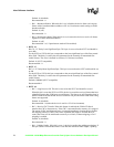
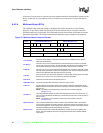
— Bit 7 - Full Duplex Pin Enable for the 82557 and 82558 A-step devices. This bit is
reserved in the 82558 B-step, 82559, 82550, and 81551 and should be set to 1b for these
devices.
When this bit is set, the device examines the FDX# pin to determine if it should operate in
full duplex or half duplex mode. If the force full duplex bit (bit 6) is set to one, then this
bit has no meaning and the device will not examine the level of the FDX# pin. This is
described in the table below.
Default - 0 (off) for the 82557 and 82558 A -step devices.
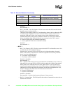
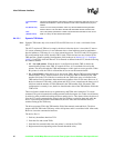
Table 49. Full Duplex Functionality
FDX PIN ENABLE
(bit 7)
FORCE FDX
(bit 6)
State of FDX#
Device Operating
Mode
0 0 0 Half Duplex
1 0 0 Full Duplex
0 1 0 Full Duplex
1 1 0 Full Duplex
0 0 1 Half Duplex
1 0 1 Half Duplex
0 1 1 Full Duplex
1 1 1 Full Duplex