


Intel 8255x 10/100 Mbps Ethernet Controller Family Open Source Software Developer Manual 45
Host Software Interface
Note: The self-test does not generate an interrupt or similar indicator to the host CPU upon completion.
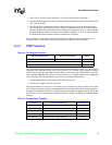
6.3.3.3 Port Selective Reset
The Port Selective Reset is useful when only the device needs to be reset and all configuration
parameters need to be maintained. The selective reset puts the CU and RU to the idle state but
maintains the current configuration parameters. The selective reset maintains RU and CU base,
HDS, error counters, configuration information, and individual and multicast addresses. As in a
Port software reset, software must wait for ten system clocks and five transmit clocks before
accessing the device (approximately 10 µs in software).
6.3.3.4 Port Dump
The Dump function writes dumped data to the specified location by the Dump Area Pointer. It is
useful for troubleshooting “No Response” problems. If the device is in a no response state, the Port
Dump operation can be executed to obtain internal device information without disturbing the rest
of the system. When the Port Dump command is completed, it writes a DWORD with the value
A006h at the end of the Dump space (Dword 149). The Dump command results format is discussed
in Section 6.4.2.7, “Dump (110b)”.
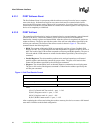
6.3.3.5 PORT Dump Wake-up
The Port Dump Wake-Up command is only available on the 82559 and later generation controllers.
It is not available on the 82558 or 82557.
After a Port Dump Wake-up command, the 82559 writes the stored data of the wake-up packet to
the host memory starting at the address specified in the pointer field. The Dump Wake-up data
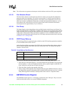
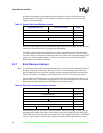
structure is shown below:
The 82559 executes the following sequence after it receives a Port Dump Wake-up command:
1. Writes the byte count field at Dword 1. This field contains the actual number of bytes posted in
the host memory. A value of FFh indicates that the wake-up packet length exceeded the 120
bytes. In this case, only the first 120 bytes are posted.
2. Writes the Wake-up packet data starting at Dword 2.
3. Writes a status word composed of the Complete OK bits (equals A000h at Dword 0). Prior to
the Dump Wake up packet command, the driver should initialize the status word to 0. After the
Dump Wake-up packet command, it should poll the status word for a completion status.
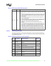
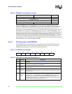
6.3.4 EEPROM Control Register
The EEPROM control register is a 32-bit entity at offset 0Ch of the CSR space. They are used to
read from and enable writes to an external EEPROM component.
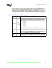
Table 20. Dump Wake-up Data Structure
Dword Offset D31 D0
0 Reserved Status Word (A000h)
1 Reserved Byte Count
2:n Wake-up Packet