


128 10/100 Mbps Ethernet Controller Family Open Source Software Developer Manual
Physical Layer Interface
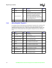
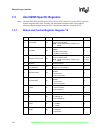
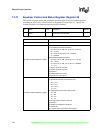
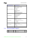
7.3.11 Equalizer Control and Status Register: Register 26
This register is used to control and monitor the operation of the 8255x PHY module equalizer
(excluding the 82557 since it does not have an integrated PHY unit). Bits 15:13 specify the
command, and bits 12:0 contain the data field for the command.
Bit Name R / W Description Default
15:0
Equalizer Control and
Status
RW
Bits 15:13 contain the opcode command while bits
12:0 hold the command data.
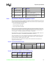
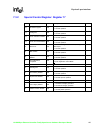
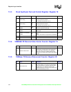
Opcode Command (bits 15:13) Command Data (bits 12:0)
000 NOP
001 Write to ASD configuration register
0
[12] Set zero command. Set value of bits 3:0.
[11:10] FSM high threshold transitions:
00 = FM: 2.19 ms; SM: 2.01 ms (0.5 ms - 2.03 ms)
01 = 2.19 ms
10 = FM:2.19; SM:2.03 (0.5 ms - disabled)
11 = Disabled
[9:8] FSM low threshold transitions:
00 = FM: 1.83 ms; SM: 1.99 ms (0.5 ms - 1.97 ms)
01 = 1.83 ms
10 = FM: 1.83 ms; SM: 1.97 ms (0.5 ms - disabled)
11 = 1 ms
[7] Signal squelch force enable.
[6] Squelch signal forcing value.
[5] Reserved.
[4] Enable/disable zero forcing.
[3:0] Coded zero 0 through 15.
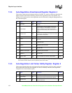
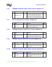
010 Write to ASD configuration register
1
[12:11] Reserved.
[10:9] TMD100 transition ration bits/LPF ratio:
00 = 0.5 / 6
01 = 0.5 / 5
10 = 0.25 / 6
11 = 0 / 6
[8:7] Signal detect 5-bit counter setting value:
00 = 10h
01 = 18h
10 = 1Ch
11 = 1Fh
[6] Set signal detect counter command.
[5] Reserved.
[4] Disable lock adaptation mechanism.
[3:1] Reserved.
[0] Force test mode and activate LFSR register.