


Intel 8255x 10/100 Mbps Ethernet Controller Family Open Source Software Developer Manual 85
Host Software Interface
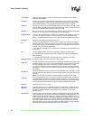
The 82558 and 82559 also offer a more advance transmit command block. When they are
configured to use extended TCBs, the device reads an 8-Dword TCB from host memory into its
internal registers instead of the standard 4-Dword TCB. The new TCB structure is composed of the
4 standard TCB Dwords followed by 2 TBDs or 2 Dwords each.
The fields in the first 4 Dwords are identical to the first 4 Dwords of the standard TCB except for
the TBD array address, which points to the third TBD rather than the first one. In other words, if
the frame consists of more than two transmit buffers, the rest of the TBDs, from the third one
onwards, are placed in a standard TBD array, which is pointed to by the TBD array address field.
The TBD number field indicates the total number of TBDs including the two TBDs located in the
latter 4 Dwords of the extended TCB. If a transmitted frame consists of less than two TBDs, the
driver can set the size field of the second (or both) TBD to zero or set the EL bit on the first TBD.
The advantage of the extended TCB is that it enables the device to read the TCB and the first two
TBDs in one 8-Dword PCI burst. This eliminates one PCI read and its associated latency and
enables both the TCB and its immediate data field to be cache line aligned.
An extended TCB is assumed to be flexible. The two TBDs that are part of the extended TCB may
use the EL bit, but it is required that the transmit buffer pointers in the two TBDs are always valid
(in other words, not equal to 0).
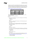
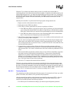
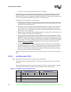
The transmit buffer descriptor (TBD) array is a contiguous structure of TBDs. A TBD is defined as
a transmit buffer address and a transmit buffer size. The format of the TBD array is shown below.
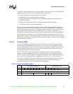
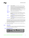
Transmit
Threshold
The transmit threshold defines the number of bytes that should be present in the
controller's transmit FIFO before it starts transmitting the frame. The value is internally
multiplied by 8 to give a granularity of 8 bytes. For example, a value of 1 means the
82557 will start transmitting only when it has 8 bytes in its transmit FIFO. The transmit
threshold should be within a range of 1 to 0E0h. (The value 0FFh should not be used.)
EOF
The EOF bit indicates if the whole frame is in the transmit command block. For
consistency, it should be set by software, although it is not checked in simplified or
flexible mode.
TCB Byte Count
For either simplified or flexible mode, the controller is able to transmit data from memory
immediately contiguous to the TCB itself. The amount of data to be read from this space
is determined by the 14-bit TCB byte count. This counter indicates the number of bytes
that will be transmitted from the transmit command block, starting with the third byte after
the TCB count field (address N + 10h). The TCB count field can be any number of bytes
up to a maximum of 2600, which allows the user to transmit a frame with a header having
an odd number of bytes. In simplified mode, the TCB byte count indicates the total
number of bytes to be transmitted and should not equal zero. In flexible mode, if the TCB
byte count equals 0, then all data is taken from the buffers pointed to by the TBD array.
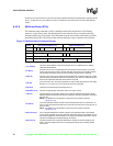
Figure 20. Transmit Buffer Descriptor
Odd Word (Bits 31:16) Even Word (Bits 15:0)
Transmit Buffer #0 Address 0
0 0 0 0 0 0 0 0 0 0 0 0 0 0 0
EL 0 Size (Actual Count) 4
Transmit Buffer #1 Address 8
0 0 0 0 0 0 0 0 0 0 0 0 0 0 0
EL 0 Size (Actual Count) C
Transmit Buffer #N Address N*8
0 0 0 0 0 0 0 0 0 0 0 0 0 0 0
EL 0 Size (Actual Count) N*8+4