


Intel 8255x 10/100 Mbps Ethernet Controller Family Open Source Software Developer Manual 27
Host Software Interface 6
The 8255x LAN controllers establish a shared memory communication system with the host CPU.
Software controls the device by writing and reading data to and from this shared memory space.
All of the LAN controller functions (configuration, transmitting data, receiving data, etc.) that are
software manageable are controlled through this shared memory space.
Note: Although references are made to both simplified and flexible memory modes for transmit and
receive commands, only the simplified mode is supported. All bit settings and silicon
configurations only refer to the simplified memory mode.
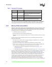
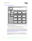
6.1 The Shared Memory Architecture
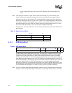
The shared memory structure is divided into three parts: the Control/Status Registers (CSR), the
Command Block List (CBL), and the Receive Frame Area (RFA). The CSR physically resides on
the LAN controller and can be accessed by either I/O or memory cycles, while the rest of the
memory structures reside in system (host) memory. The first 8 bytes of the CSR is called the
System Control Block (SCB). The SCB serves as a central communication point for exchanging
control and status information between the host CPU and the 8255x. The host software controls the
state of the Command Unit (CU) and Receive Unit (RU) (for example, active, suspended or idle)
by writing commands to the SCB. The device posts the status of the CU and RU in the SCB Status
word and indicates status changes with an interrupt. The SCB also holds pointers to a linked list of
action commands called the CBL and a linked list of receive resources called the RFA. This type of
structure is shown in the figure below.