


118 10/100 Mbps Ethernet Controller Family Open Source Software Developer Manual
Physical Layer Interface
This structure allows a controller, or other management hardware, to query the PHY for the status
of the link or configure the PHY to one of many modes. The next section discusses the MDI
registers.
7.2 MDI Register Set
The generic MDI register set is defined as follows:
The Intel
®
82555-specific (and thus 82558 and 82559 specific as well) MDI registers are listed in
the table below. (These registers also apply to the 82558 and 82559.)
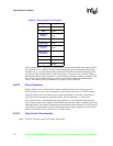
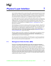
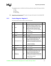
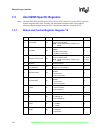
Figure 26. Management Frame Structure
Start Opcode PHY Address Register Address Transition Data
READ < 01 > < 10 > < AAAAA > < RRRRR > < Z0 > 16 Bits
WRITE < 01 > < 01 > < AAAAA > < RRRRR > < 10 > 16 Bits
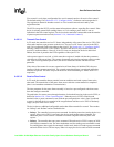
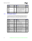
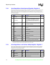
Table 59. MDI Register Set
Register Address Register Name and Function
00000 Control Register (MDI Standard Register)
00001 Status Register (MDI Standard Register)
00010 PHY Identification Register (Word 1)
00011 PHY Identification Register (Word 2)
00100 Auto-Negotiation Advertisement Register
00101 Auto-Negotiation Link Partner Ability Register
00110 Auto-Negotiation Expansion Register
00111-01111 Reserved
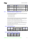
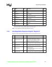
Table 60. 82555 MDI Register Set
Register Address Register Name and Function
10000 Status and Control
10001 Special Control
10010 Clock Synthesis Test and Control
10011 100BASE-TX Receive False Carrier Counter
10100 100BASE-TX Receive Disconnect Counter
10101 100BASE-TX Receive Error Frame Counter
10110 Receive Symbol Error Counter
10111 100BASE-TX Receive Premature End of Frame Error Counter
11000 10BASET Receive End of Frame Error Counter
11001 10BASE-T Transmit Jabber Detect Counter
11010 Equalizer Control and Status
11011 Special Control