


102 Intel 8255x 10/100 Mbps Ethernet Controller Family Open Source Software Developer Manual
Host Software Interface
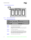
6.4.3.2 Initial Receive Frame Area Structure
To enable the device to receive frames, software must setup the following structure:
1. The SCB general pointer in the SCB should point to the first RFD on the list.
2. The link offset of each RFD in the list should point to the next RFD.
3. The EL bit in the last RFD should be set.
6.4.3.3 Operation of Frame Reception
The serial subsystem of the device selects the frames destined for the station according to the
destination address of the frames passing on the link. A frame is selected if it is at least 6 bytes long
and its address matches either the individual address, multicast address, multiple IA, or broadcast
address (promiscuous mode). It transfers the selected frames with their status to the receive FIFO.
The receive DMA unit transfers the frame from the receive FIFO to host memory under control of
the receive unit. If discard short frames is enabled, any receive frame shorter than 64 bytes on the
link (including padding and CRC) will be completely discarded. Although these frames are
discarded, they are still counted in the short frame counter.
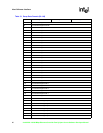
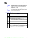
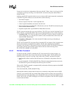
Bit 2
No address match. If this bit is set to 1, the destination address of the received frame does not
match the individual address, multicast address, or the broadcast address in the filter. For
example, this bit will be set when the device is in promiscuous mode and the destination address
does not match any of the other address filtering mechanisms.
Bit 1
IA match bit. When this bit equals 0, it implies that the destination address of the received frame
matches the individual address. When it is 1, the destination address of the received frame does
not match the individual address. For example, a multicast or broadcast address will set this bit to
a 1.
Bit 0
Receive collision (82557 and 82558 only). When this bit is set, it indicates a collision was detected
during a reception.
TCO indication (82559 and later generation controllers). For the 82559 and later generation
controllers, this bit no longer reflects collision detection. Instead, it indicates that the device is
processing a TCO packet. In an environment with a TCO controller where receive to TCO is
enabled, the controller introduces a new behavior. TCO packets are first posted to the RFA before
they are transferred back to the TCO controller. In most cases this process is completely
transparent to the software driver since the RFD that contains the TCO packet is reclaimed.
However, if header RFDs are being used and the TCO packet size is larger than the header size,
then the RFD is not reclaimed. In this case, a bad status indication will be posted to memory. The
bad status indication should be used by the software driver to discard the packet.
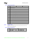
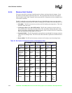
Table 53. Actual Count in Header RFD
FEOF Actual Count
00Invalid
01Invalid
10HDS size
1 1 Total byte count
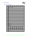
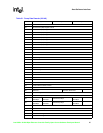
Table 52. RFD Status Bit Descriptions
Status
Bit
Description