


•
See Switch Fabric and Routing Engine (SRE) Module in an EX8208 Switch.
•
See Routing Engine (RE) Module in an EX8216 Switch.
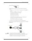
4. Connect the other end of the cable to the RJ-45 to DB-9 serial port adapter supplied
with your switch.
5. Connect the serial port adapter to the DB-9 female to DB-25 male adapter or other
adapter appropriate for your modem.
6. Plug the modem adapter into the DB-25 connector on the modem.
7. Connectoneendofthephonecabletothemodemandtheotherendtoyourtelephone
network.
8. Turnon the power to your modem.
9. Power on the switch.
Related
Documentation
Connecting an EX Series Switch to a Management Console on page 76•
• Console Port Connector Pinout Information for an EX Series Switch on page 21
Connecting a Fiber-Optic Cable to an EX Series Switch
EX Series switches have field-replaceable unit (FRU) optical transceivers to which you
can connect fiber-optic cables.
Before you begin connecting a fiber-optic cable to an optical transceiver installed in an
EXSeriesswitch,ensurethatyouhavetakenthenecessaryprecautionsforsafe handling
of lasers (see “Laser and LED Safety Guidelines and Warnings for EX Series Switches”
on page 121).
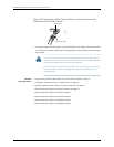
To connect a fiber-optic cable to an optical transceiver installed in an EX Series switch:
WARNING: Donot lookdirectly intoa fiber-optic transceiveror into the ends
offiber-opticcables.Fiber-optictransceiversandfiber-opticcablesconnected
to transceivers emit laser light that can damage your eyes.
1. If the fiber-optic cable connector is covered by a rubber safety cap, remove the cap.
Save the cap.
2. Remove the rubber safety cap from the optical transceiver. Save the cap.
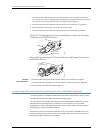
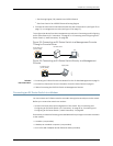
3. Insert the cable connector into the optical transceiver (see Figure 35 on page 82).
81Copyright©2010, JuniperNetworks, Inc.
Chapter10:Connectingthe Switch