


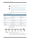


Table 22: Inventory of Components Provided with an EX2200 Switch (continued)
QuantityComponent
8Mounting screws
4Rubber feet
1RJ-45cableand RJ-45toDB-9 serial port adapter
Related
Documentation
Mounting an EX2200 Switch on page 53•
• Installing and Connecting an EX2200 Switch on page 51
• Connecting and Configuring an EX Series Switch (CLI Procedure) on page 87
• Connecting and Configuring an EX Series Switch (J-WebProcedure) on page 89
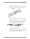
Mounting an EX2200 Switch
You can mount the switch:
•
On two posts in a 19-in. rack or cabinet by using the mounting brackets provided with
the switch.
•
On four posts in a 19-in. rack or cabinet by using the separately orderable four-post
rack-mount kit.
•
In a position recessed 2 in. from the front of a 19-in. rack or cabinet by using the
2-in.-recess front brackets in the separately orderable four-post rack-mount kit. You
can mount the switch in this recessed position on two-post or four-post racks and
cabinets.
•
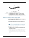
On a desk or other level surface by using rubber feet. The switch is shipped with four
rubber feet to be used to stabilize the chassis on a desk or other level surface.
•
On a wall by using the separately orderable wall-mount kit.
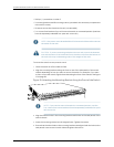
WARNING:
•
When mounting an EX2200 switch chassis in a vertical position, orient
the front panel of the chassis downward to ensure proper airflow and
meet safety requirements in the event of a fire.
•
When wall mounting Power over Ethernet (PoE)models (EX2200-24P
andEX2200-48P),installthewall-mountbaffleabovetheunitstoreduce
the risk of objects or substances falling into the air exhaust or power
supply, which could cause a fire.
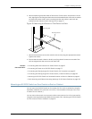
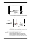
The holes in the mounting brackets are placed at 1 U (1.75 in. or 4.45 cm.) apart so that
the switch can be mounted in any rack or cabinet that provides holes spaced at that
distance.
53Copyright©2010, JuniperNetworks, Inc.
Chapter8:Installing theSwitch