


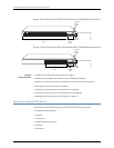
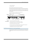


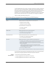

Figure1: FrontPanel of an EX2200 Switch with 48 Gigabit Ethernet Ports
0
1
2
3
4
5
6
7
8
9
10
11
12
13
14
15
16
17
18
19
20
21
22
23
24
25
26
27
28
29
30
31
32
33
34
35
36
37
38
39
40
41
42
43
44
45
0 1 2
SYS
ALM
SPD
DX
EN
POE
3
46
47
Network
ports
Port status mode LEDs
Mode
button
SFP
uplink
ports
Chassis
status
LEDs
g027000
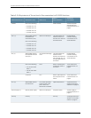
Figure2: Front Panel of an EX2200 Switch with 24 GigabitEthernet Ports
0
1
2
3
4
5
6
7
8
9
10
11
12
13
14
15
16
17
18
19
20
21
22
23
0 1 2
SYS
ALM
SPD
DX
EN
POE
3
Network
ports
Chassis
status
LEDs
g027002
SFP
uplink
ports
Port status mode LEDs
Mode
button
Related
Documentation
Chassis Status LEDs in EX2200 Switches on page 11•
• Network Port and Uplink Port LEDs in EX2200 Switches on page 12
• Network Port Connector Pinout Information for an EX2200 Switch on page 20
• Rear Panel of an EX2200 Switch on page 6
• Installing a Transceiver in an EX Series Switch on page 65
• Removing a Transceiver from an EX Series Switch on page 95
• Installing and Connecting an EX2200 Switch on page 51
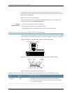
Rear Panel of an EX2200 Switch
The rear panel of the EX2200 switch consists of the following components:
•
Management Ethernet port
•
USB port
•
Console port
•
Protective earthing terminal
•
ESD point
•
Air exhaust
Copyright ©2010,Juniper Networks,Inc.6
CompleteHardwareGuide forEX2200 EthernetSwitches